Water pressure on a slab with varying thickness

I have modelled a submerged tunnel in Sofimshc in 3D.
The quad elements used are placed in the centreline of each slab and wall, as seen here:

Now I want to add water pressure to the topslab, which I have defined using free area loads like this.

AREA REF QGRP 'Top' Proj 'yy' WIDE 500[m] TYPE 'pzz' P1 0    X1 0    Y1 0 Z1 0    $$
                                                     P2 0    X2 1000 Y2 0 Z2 0    $$
                                                     P3 -100 X3 1000 Y3 0 Z3 -100 $$
                                                     P4 -100 X4 0    Y4 0 Z4 -100 

Unfortunately, as slabs vary in thickness, this method will result in higher water pressure in the areas highlighted in red.

Is there a clever way around this?

If the topslab has its own groupnumber, you could use “grp facd” (in this special loadcase) as difference:

  • grp no - facd 0; grp no “top” facd “special value”
  • lc no “waterpressure-No.”
  • AREA REF QGRP 'Top' Proj 'yy' ...
    

But this don’t work in summary-loadcases with FACD also in LC.

When your outer walls are thick or the pressure high, you should probably calculate with real loadareas (loads “behind” the systemlines / the half wallthickness).

sorry, but I’m not sure I understand your comments.

  1. My topslab has its own group number (secondary group) ‘Top’.
    But do you mean that the areas where the thickness varies should have separate group numbers?

I have considered adding negative loads there based on the thickness, but I was hoping for a better solution.

  1. When you write “real loadareas” do you mean load distribution areas?
  1. ‘top’ alone / the entire topslab is good, you don’t need extra groups / it is better without such.
    (Yet to “grp no top facd …”: a additional disadvantage is, this works only for pressure in the system-deadload-direction.)
  2. The system-width is smaller then the real outer limits. By calculation with system-width you undercharge the overall-pressure / the vertical load in the outer walls.
  1. Can you give an example of how you would apply this factor? I still don’t quite follow.
    Also, when you say it only works in the deadload direction, does that mean I can’t use it in the base slab, as I need to apply it in the opposite direction there?

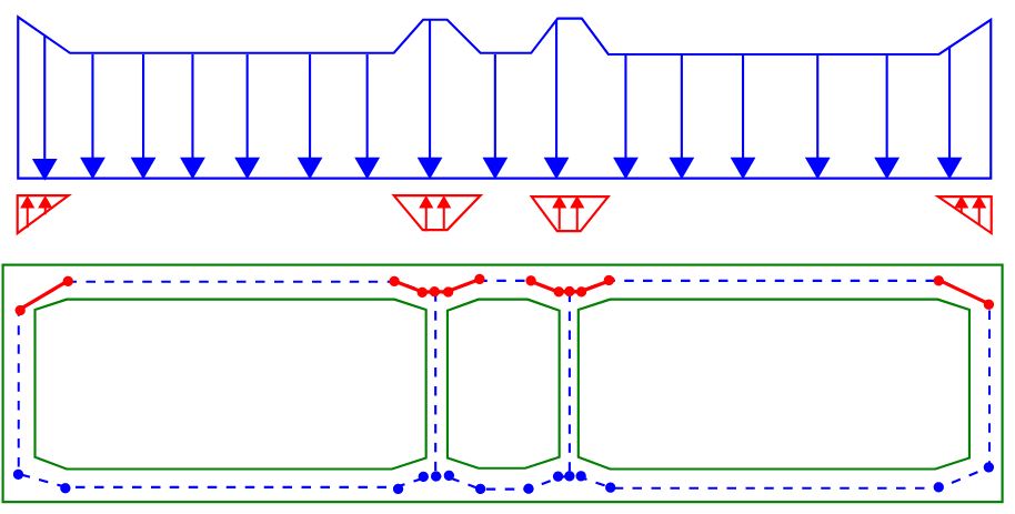
  2. ahh yes, this has been taken into account with stiff members from center line to the outer edge of the element, but I didn’t show it in the drawings as I figured that would only confuse :slight_smile:

+prog sofimsha urs:2
 head test
 syst spac gdiv 1000
 node   1,02,03   x  0,2,5   y 0     z 0,-0.50,-0.50
       11,12,13   x  =       y 3     z =
 grp 01 titl 'top'
 quad -  1  11  12  2  m 5 n 6  t1 1.50[m]  t2 1.50[m]  t3 0.50[m]  t4 0.50[m]  c 20  ct 1
      -  2  12  13  3  m - n 7  t  0.50[m]                                      c  =  ct =
end
+prog sofiload urs:3
 lc no 19  titl 'preparation 10 kN/m² lower edge'; quad grp 01 p (10+0.50*25)  $ target: 10; additional deadload of the "main slab"
end
+prog ase urs:4
 lc 19; end
 grp - facd 0; grp no 01 facd -1
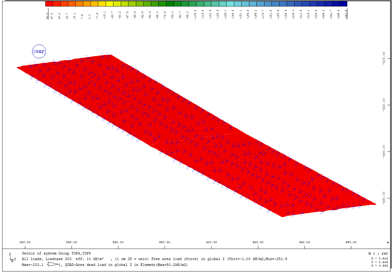
 lc 20 titl 'eff. 10 kN/m²'; lcc 19
end

The combined loadcase 20:

Disadvantage deadloaddirection: It works not for other (like horizontal) directions.

If I’m applying this correctly, it doesn’t do the trick.

My implementation looks like this:

+prog sofiload
AREA REF QGRP 'Top' Proj 'yy' WIDE 500[m] TYPE 'pzz' P1 0    X1 0    Y1 0 Z1 0    $$
                                                     P2 0    X2 1000 Y2 0 Z2 0    $$
                                                     P3 -100 X3 1000 Y3 0 Z3 -100 $$
                                                     P4 -100 X4 0    Y4 0 Z4 -100 
end
+prog ase urs:4
 lc 202; end
 grp - facd 0; grp no 'Top' facd -1
 lc 203 titl 'eff. 10 kN/m²'; lcc 202
end

As far as I can tell, the problem is that my depth is not constant either:
image

At least I get the following applied loads:

Load case 202:

Load case 203:

I think it works, but maybe, you don’t see it, because you see not all loads.
Here is my input for the output:

PROG WING
$ GRAPHIC-Dokument (Version 2022- 6.00 Build       0)
HEAD $Mittlere QUAD-Elementdicke
PAGE UNII 0 $ Standard-Einheitenset
CTRL OPT GSTR VAL DEFA
CTRL OPT REPR VAL YES
$ DB   NR 1 BEZ "xxxx.cdb"
$ Grafik    1 | Bild    1 | Layer    1 : Mittlere QUAD-Elementdicke
PAGE LANO 0
SIZE TYPE URS SC 0
SIZ2
AND  POSI 1 POSL 0 POSR 100 POSD 0 POSU 100
SCHH H6 -0.160000
SCH2 DIRE STAN
LC   NO 20 DESI 1
BOX
GRP NUMB KNOT OPTI OFFL
GRP NUMB FKNO OPTI OFFL
GRP NUMB EDGE OPTI OFFL
GRP LC YES
VIEW TYPE DIRE X 0 Y -1 Z 0 AXIS POSZ ROTA 0
DEFO TYPE NO EXPO 0 SMOV NO
SELE NUMB 0
STRU NUME T NUMN QUAD FILL NO REPR DVEC UNIT LFAC SCHH NO
$ Grafik    1 | Bild    1 | Layer    2 : Alle Lasten  LF:         20
AND
SCHH H6 0.370000
SCH2 DIRE STAN EDGE NO PREF NO PROP 'B'
QUAD TYPE DSGN COMT NO
LOAD TYPE ALL UNIT DEFA SCHH YES SING VECT FILL NO REPR DREP ETYP ALL GTYP INP
END

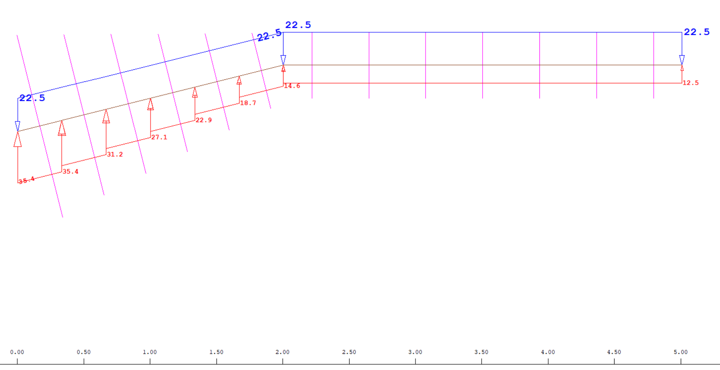
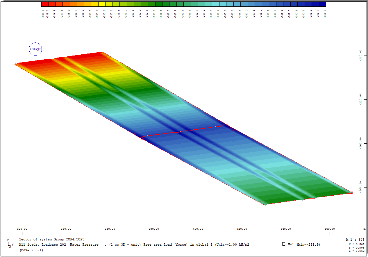
And this are the loadsumms (in global z):
LC 19: -341.7 kN
LC 20: -74.5 kN

The grp-fcd should work without backlash to AREA-loads respectively revers. Also by AREA and WITH. Although i had sometimes programm-troubles with WITH.
Or it is possibly your deadload-direction “yy” (but it must not).

I ended up applying the load seperately using the array defining the top slab.

Thereby my final code ended up being:

+prog sofiload
LC 202 TYPE 'Q' TITL 'Water Pressure'
AREA REF QGRP 'Top' Proj 'yy' WIDE 500[m] TYPE 'pzp' P1 0    X1 0    Y1 0 Z1 0    $$
                                                     P2 0    X2 1000 Y2 0 Z2 0    $$
                                                     P3 -100 X3 1000 Y3 0 Z3 -100 $$
                                                     P4 -100 X4 0    Y4 0 Z4 -100 


! Database calcs
@key NODE
loop#i #nelem
    let#nr @(#i+2,NR)
    let#x(#i) @XYZ
    let#y(#i) @(XYZ+1)
    let#z(#i) @(XYZ+2)
endloop

! X-coordinates of the tunnel corresponding to the water level
let#XWaterN (#ZWater-(#z(0)-#db+#h))*(#x(1)-#x(0))/(#z(1)-#z(0))+#x(0)
let#XWaterS (#ZWater-(#z(8)-#db+#h))*(#x(8)-#x(7))/(#z(8)-#z(7))+#x(8)

LC 203 TYPE 'Q' TITL 'Inc. waterpressure due to inc. thickness of slab'

    loop#i #len_P-1 ! Length of #P array -1
        let#i #i+1
        AREA REF QGRP 'Top' Proj 'zz' WIDE 500 TYPE 'PZP' P1 -#P(#i-1) X1 #XWaterN Y1 #Y_T(#i-1) Z1 0  $$ ! #Y_T is y-coordinate of each node in the topslab. #P is load at each point.
                                                          P2 -#P(#i-1) X2 #XWaterS Y2 #Y_T(#i-1) Z2 0  $$ 
                                                          P3 -#P(#i)   X3 #XWaterS Y3 #Y_T(#i)   Z3 0  $$
                                                          P4 -#P(#i)   X4 #XWaterN Y4 #Y_T(#i)   Z4 0


LC 204 TYPE 'Q' TITL 'Final water pressure'
    COPY LC 202
    COPY LC 203
end

Please note that some variables are missing, this is just an excerpt to help others having similar issues in the future.