Dear all,
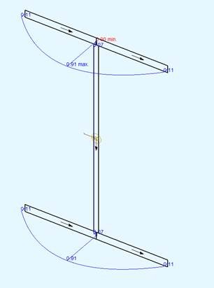
I have loaded a cantilever at the tip with a single torsional moment and activated warping torsion with ctrl warp 1 using version 2020. Now, for the given configuration, only shear stresses due to the torsional moment result at the restraint from torsion, the resultant of which represents the secondary torsional moment accordingly. In the Result Viewer, under unit shear stress from secondary torsional moment, it is of course correctly displayed how the stresses should run. However, if you look at the stresses in the Result Viewer under results - cross sections- stresses, the same sign appears both at the lower and upper flange (and slightly increased values, the difference between which, however, also corresponds to the stress bulge in the unit stresses, but I still cannot quite understand where the 0.11 comes from). The local sheet coordinate is shown by the arrows - can you give us an explanation for the discrepancies in these results? Code is inserted here, as as new member I can not attach any files…
Picture of the wrong stresses (at least according to my opinion): The shear stresses here should form the secondary torsional moment, but here they are outbalancing any torsional effects according to sign and stress direction.

################################################################
$Autor: Drilon Gubetini, Überprüfung WKT SOFiSTiK
+prog aqua urs:1
head Material und Querschnitt
NORM EN 1993-2005
STEE NO 1 TYPE S CLAS 355
SECT 1 MNO 1
PLAT YB 150[mm] ZB -207.5[mm] YE 0 T 15[mm]
PLAT YE -150[mm] T 15[mm]
PLAT YB 0[mm] ZB -200[mm] ZE 200[mm] T 10[mm]
PLAT YB 150[mm] ZB 207.5[mm] YE 0 T 15[mm]
PLAT YE -150[mm] T 15[mm]
WELD ZB -207.5[mm] YB 0 ZE -200[mm] T 0.003[m] mno 1
WELD ZB 207.5[mm] YB 0 ZE 200[mm] T 0.003[m] mno 1
END
+prog sofimsha urs:2
head System
syst 3D GDIV 1000 GDIR NEGZ
STO#L 5
$ Knoten
LOOP#I 126
NODE NO 1+#I X #I*#L/125 Y 0 Z 0
ENDLOOP
LOOP#I 125
BEAM NO 1+#I NA 1+#I NE 2+#I NCS 1
ENDLOOP
NODE NO 1 FIX F
END
+prog sofiload urs:3
head
LC NO 1
NODE NO 126 TYPE MXX 1 $-5.625
end
+prog ase urs:4
head
ctrl warp 1
lc 1
end
+prog aqb urs:5
head Vglspannungen
LC NO 1
stre smod e
end
############################################################################
Thanks in advance for your help
Best
Drilon
