I want to define the rotational spring stiffness of the springs as half of the bending stiffness of the plate but I can’t get my head around how to define this properly.
The bending stiffness of the plates are E*I [kNm²], and naturally I would apply half of that value as my spring stiffness. However, in the sofimshC manual, it says that I should give a value of unit [kN/rad]. I’ve also thought that I might need to apply a value per spring length, but that still brings me to [kNm] and not [kN/rad].
Hi,
this is not as simple as you described in general.
I assume you want to introduce some kind of elastic hinges in to the plate.
Springs can add something like additional rotation to your slab, but if you want to refer it to slab stifness in mean of reduction you have to anwser the question how long is reduced stifness zone which is needed to calculate addtional rotation → rotational stifness. Another easier way is to define this zone with lower thickness or with reduced stifness f.e. by GRP FACS in ASE
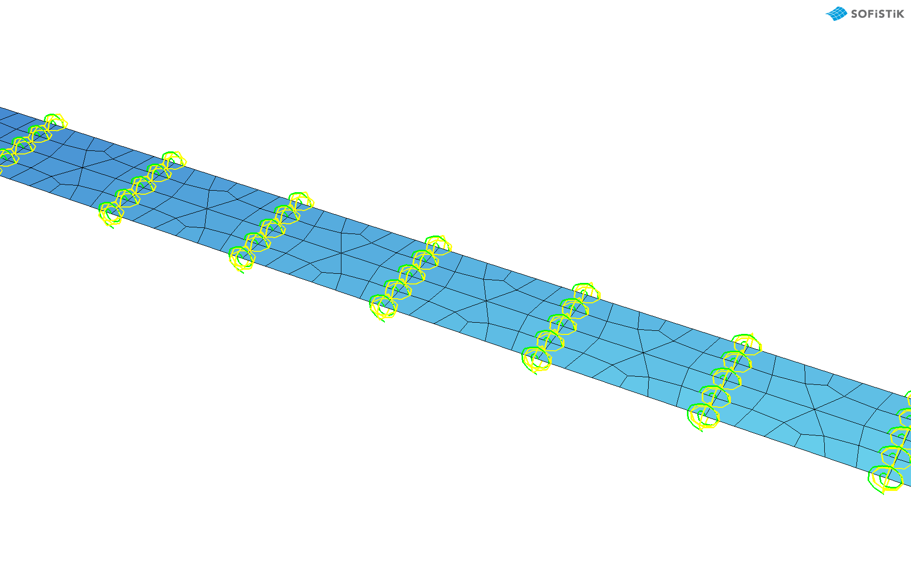
What I want to simulate is a timber strip with some cuts in it. I was thinking of your approach already, to model the area with less bending thickness with shell elements with lower thickness, however since the region is really a cut and this 1-3mm wide, that will make the number if elements explode, since they need to be extremly small in those regions. This is why a well defined rotational spring should be the best approach.
Could you please try to clarify this?
if you want to refer it to slab stifness in mean of reduction you have to anwser the question how long is reduced stifness zone which is needed to calculate addtional rotatio
Do you mean that I should include the “width” of my cut in the calculation of the spring stiffness?
Yes, I mean if you do not have a cut those spring have infinite stiffness.
If you have the cut those spring have some stiffness which causes bigger rotation. Spring stiffness depends on width and height of cut. Some mathematics is to do here.
As I explained before it is not sofistik problem anymore but rather structural mechanics one.
If basic height is H, cutted is h and length of cut is L I woudl estimate additional rotation causes by moment M=1 as
phi=12L/h^3 - 12L/H^3
and k=1/phi
prog aqua urs:1
head
norm en 1992-2004
conc no 1 c 30 ec 30000 mue 0.0
end
+prog sofimsha urs:2
head
syst spac gdiv 1000
let#B 1
let#L 0.01
let#h1 1.00
let#h2 0.20
node 11,21,31,41 x 0,2-#L/2,2+#L/2,4 y -#B/2 z 0
node 12,22,32,42 x 0,2-#L/2,2+#L/2,4 y +#B/2 z 0
node 11 fix f
node 12 fix pxpzmy
quad fit 11 21 22 12 m 5 n 1 t #h1[m]
quad fit 21 31 32 22 m 1 n 1 t #h2[m]
quad fit 31 41 42 32 m 5 n 1 t #h1[m]
node 111,121,131,141 x 0,2-0.001,2,4 y 3-#B/2 z 0
node 112,122,132,142 x 0,2-0.001,2,4 y 3+#B/2 z 0
node 111 fix f
node 112 fix pxpzmy
quad fit 111 121 122 112 m 5 n 1 t #h1[m]
quad fit 131 141 142 132 m 5 n 1 t #h1[m]
node 121 fix kp,kmx,kmz 131
node 122 fix kp,kmx,kmz 132
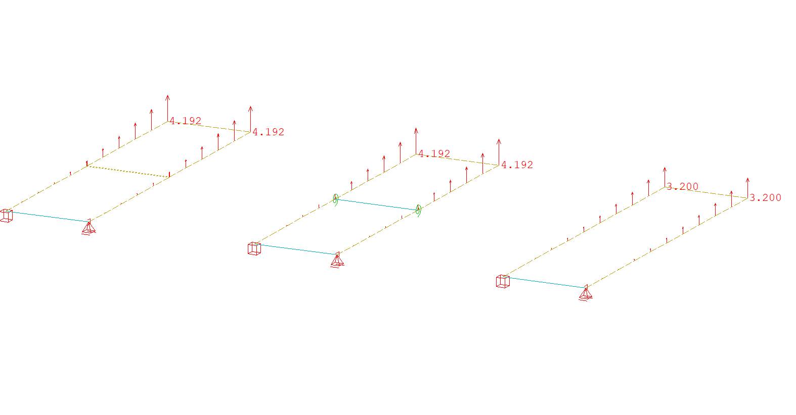
let#phi 12*#L/(30e6*#h2^3)-12*#L/(30e6*#h1^3)
spri 1,2 121,122 131,132 dy 1 cm 1/#phi*(#B/2)
node 211,221 x 0,4 y 6-#B/2 z 0
node 212,222 x 0,4 y 6+#B/2 z 0
node 211 fix f
node 212 fix pxpzmy
quad fit 211 221 222 212 m 10 n 1 t #h1[m]
end
+prog sofiload urs:3
head
lc 1
node 41,42,141,142,221,222 type myy p1 500
end
+prog ase urs:4
head
lc 1
end
it is not sofistik problem anymore but rather structural mechanics one
yes of course, but I was hoping that they could help me derive the definition of the spring stiffness and thus help me understand the mechanics.
I tried your code and its a good benchmark example indeed. However, did you get it to run and if so, did you achieve the same results?
The variable #phi was not defined, so I defined it as you suggested
phi=12L/h^3 - 12 L/H^3
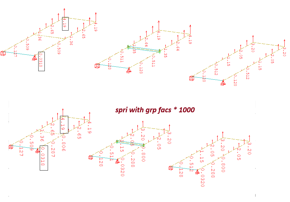
That lead to large rotations and the analysis didn’t converge however. I then had a look at the units, and when multiplying 1/#phi with #B/2 (as in your code) that resulted in [m³]. Multiplying this with the E-modulus however, brings us to [kNm] which is the correct unit, and also gives the correct results (see below).
Where 12L/H³ comes from I know, but why we take the difference, I don’t understand. Intuitively I would’ve taken 12L/h³, could you try to explain this? And also, why do we multiply with #B/2 and not #B?
Yes, I accidentaly deleted let#phi when cleaning the code, E modulus also should be accounted there:
let#phi 12*#L/(30e6*#h2^3)-12*#L/(30e6*#h1^3)
The diffrence is because additional rotation is caused by stiffness difference of cutted and uncutted quad.
B/2 because there are 2 spring on total width.
I’ve now set up a similar benchmark analysis that works fine, and I have the full control of the rotational spring stiffness.
There is ine last thing that I can’t rap my head around though. If I want to analyse an uncut plate strip but model it with many strips coupled with rotational springs, I need to assign an infinite large spring stiffness, why is that? I am thinking that the maximum deflection at the tip is the accumulated rotation of each element, but if I at some points define an infinte rotational stiffness, there should be no rotation around that axis, and thus lead to a smaller deflection, however that is not the case.
@mico do you think you could help me out with this one too?
If you model cuts by addtional springs those spring cause additional rotations. If spings stifness is infinite or high enough slab is going to act like without the cuts
Yes, I think I get it. I really need to think of the springs causing additional rotation, as you are saying. They can not make the plate stiffer than it is.
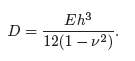
Last question, from where do you acctually derive 12L/(EH³) ? The flexural rigidity of a plate is
which is somewhat similar, but not really. Could you please explain that @mico?
For simplicity of showcase I assumed mue=0.0
If mue>0 then you can use 1/(1-mue^2) correction factor, however I am aware if the results will be correct due to distrurbance of stress in perpendicular direction.
Dear @mico , you helped me some months back on this issue regarding couplings/spring elements. I have a related problem that I posted under this thread: Orient rotational springs to follow the deformation
would you possibly have an idea of how to solve that too?