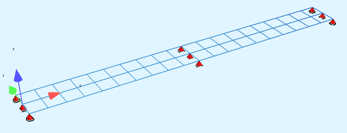
I have a grillage structure including 3 longitudinal girders and several transverse beams. The spacing of adjacent girders is 1.0m.
The center of lane is on the central girder. Below is the ELLA code
| +PROG |
ELLA |
|
|
|
|
|
| HEAD |
|
|
|
|
|
|
| ECHO |
OPT |
LANE |
VAL |
FULL |
|
|
|
|
|
|
|
|
|
| GAX |
NO |
S |
X |
Y |
Z |
|
|
LAX |
0 |
0 |
0 |
0 |
|
|
LAX |
20 |
20 |
0 |
0 |
|
| LANE |
NO |
SA |
SE |
YCA |
YRA |
YLA |
|
LAX.1 |
0 |
20 |
0 |
1 |
-1 |
| LSEL |
NO |
INT |
|
|
|
|
|
LAX.1 |
2 |
|
|
|
|
| CALC |
TYPE |
LMAX |
LMIN |
|
|
|
|
UZ |
11 |
12 |
|
|
|
|
VZ |
21 |
22 |
|
|
|
|
MY |
31 |
32 |
|
|
|
| ACT |
TYPE |
GAMU |
GAMF |
SUP |
|
|
|
VE |
1 |
1 |
EXCL |
|
|
| LC |
NO |
10 |
TYPE |
VE |
|
|
| TRAI |
TYPE |
WIDT |
|
|
|
|
|
USER |
2 |
|
|
|
|
| TRPL |
P |
|
NW |
B |
|
|
|
100 |
|
2 |
2 |
|
|
| SAVE |
100 |
|
|
|
|
|
| CASE |
1 |
|
|
|
|
|
|
POSL |
LAX.1 |
10 |
|
|
|
As you can see from the above code, the NW (wheel nunber of each axis) =2 and B (wheel spacing) =2m, so the actual wheel loads should act on the left and right girders instead of the central girder.
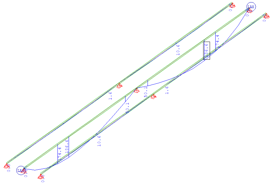
But the result moment shows that all the wheel loads are on the central girder
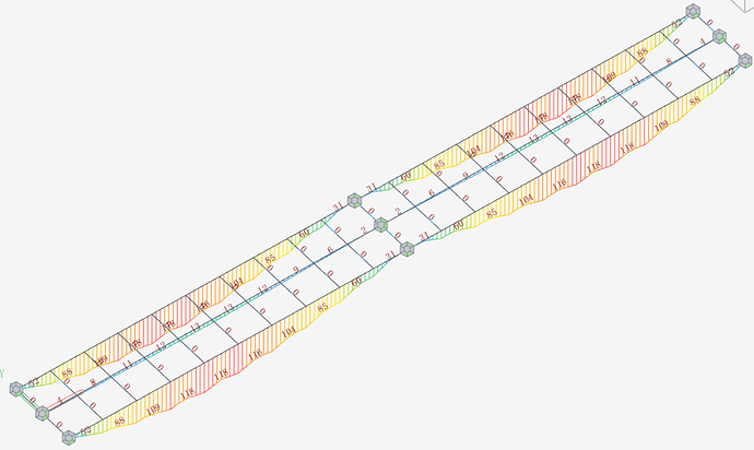
I made a same model in Midas Civil, the moment result shows that the wheel loads act on the side girders instead of the central girder
How to get the similar result as Midas Civil in Sofistik?
The behaviour depends from the boundary conditons…
Input LSEL… INT 2 means that two node sequences are searched to be loaded, see ELLA manual figure 2.7.
Now look at figure 2.4 and imagine: If there would be a lane with its midpoint exactly above of the mid girder and the node sequences of the left and the mid gorder are taken, all loads would be applied onto the mid girder (compare also figure 2.3). And then we would get the behaviour that you describe. With ECHO LANE EXTR in ELLA you find in Reportbrowser output the info about the used node sequences.
With LSEL… RSEL EDGE RSEQ [number right edge] RSEQ EDGE LSEQ [number of left edge] you can define exactly which node sequences shall be used. The number of edge can be defined before in SOFiMSHC by defining a SLN along the whole girder (along the whole superstructure). This SLN can be positioned over the already defined (shorter) SLNs with the cross sections and this SLN has no further properties.
This should help.
1 Like
Thanks JE
The SLNs are dummy beams with very weak/small cross section, so they won’t affect the stiffness of the whole structure.
But these weak dummy beams will cause issue in dynamic analysis, because of their very weak stiffness.
Therefore the best solution is not to add dummy beams. Using Node (SofimshA) or SPT (SofimshC) is the best option. The LSEL allows EDGE (nodal sequences), but this option is best for SofimshA model. As for SofimshC model, user don’t define the nodes, so they can‘t use EDGE with sofimshC model.
Is it possible to add SPT option in LSEL in the future version?
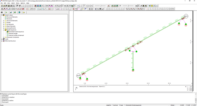
Attached you get one of our standard examples. Open SSD, start SOFiPLUS and export. Then look into task “Define EDGE 201 for ELLA”: There I add simply a SLN referenced to axis AXIS with number 201 - without other properties, so I don’t create dummy-beams. After calculating it we find in Graphic this number, see 01.
In my opinion this is the simpliest way.
PSC_Bridge.sofistik (139.0 KB)
PSC_Bridge.dwg (222.2 KB)
psc_bridge.gra (755 Bytes)
Thanks JE
I have some questions about the model
- “SLN 201 ref AXIS” This means SLN 201 is in the same location as “AXIS”. What if I want to create SLN that is off the AXIS?
- In the ELLA, I can’t find SLN 201 in LSEL
LSEL AXIS INT 0 DZ 0.1 $ RSEL GRP 0
My model is attached.
I define 2 SLNs with GRP 500 and 600, the SLNs are in the wheels location
SLN 1000 GRP 500 SNO - DRX 0.000000 0.000000 -1.000000
SLN 1001 GRP 600 SNO - DRX 0.000000 0.000000 -1.000000
Then I put them in LSEL
| LSEL |
NO |
INT |
RSEL |
RSEQ |
LSEL |
LSEQ |
|
LAX.1 |
1 |
GRP |
600 |
GRP |
500 |
As you can see, the 2 SLNs have no cross section, then it shows error when running analysis
Please run “0. include.dat” in the attachment
0. include.dat (103 Bytes)
Aqua.dat (313 Bytes)
ASE.dat (125 Bytes)
Ella.dat (600 Bytes)
SofimshC.dat (16.4 KB)
Hi netsonic,
I did not check your example, because I think the following hints already help.
My example should only show that the number of the SLN is the number of the EDGE, not more. This edge is not used within ELLA in my example!
Earlier I wrote you shall define in ELLA:
LSEL… RSEL EDGE RSEQ [number right edge] RSEQ EDGE LSEQ [number of left edge]
=> So you must reference to the EDGE number, not to a group of beams!
I hope now it’s clear.


