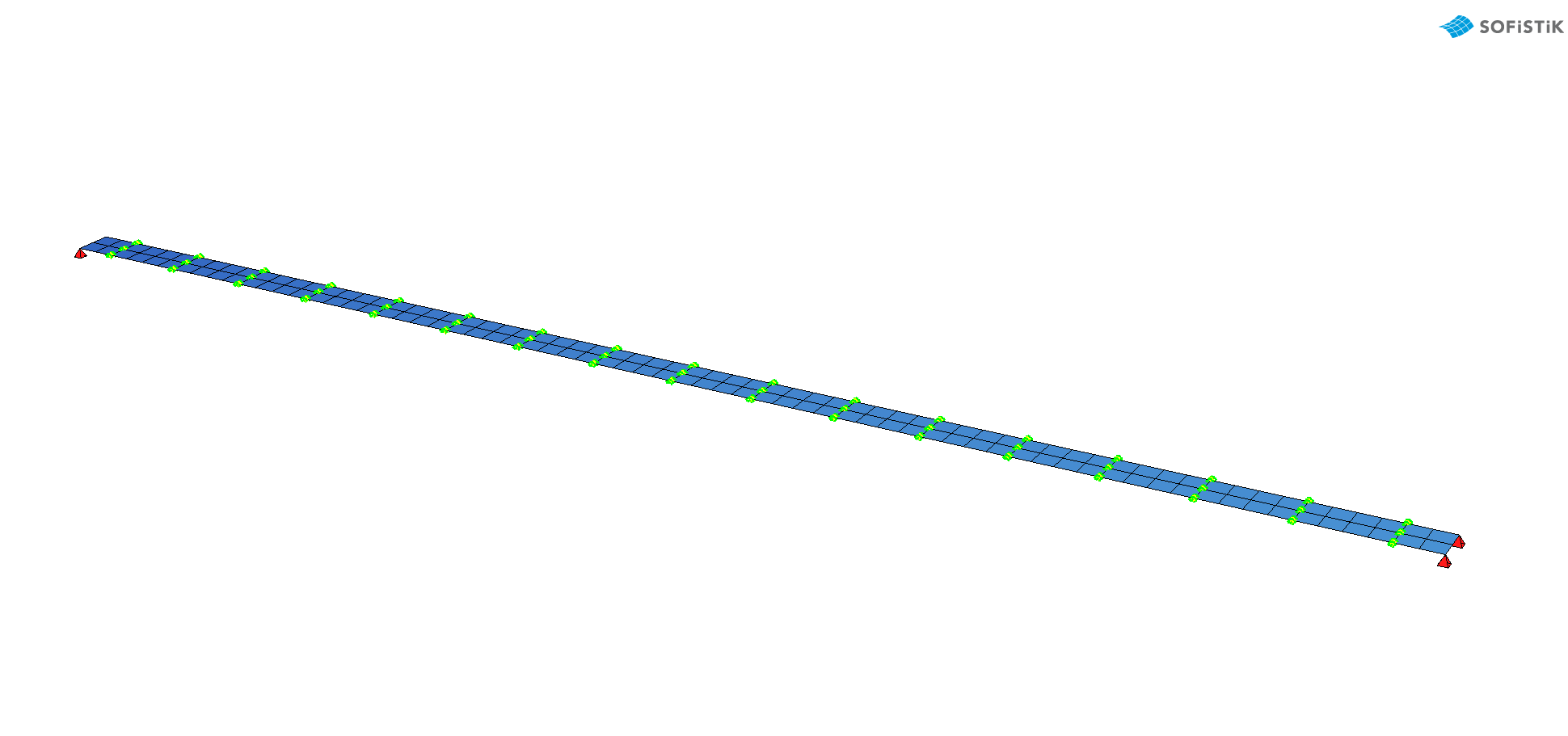
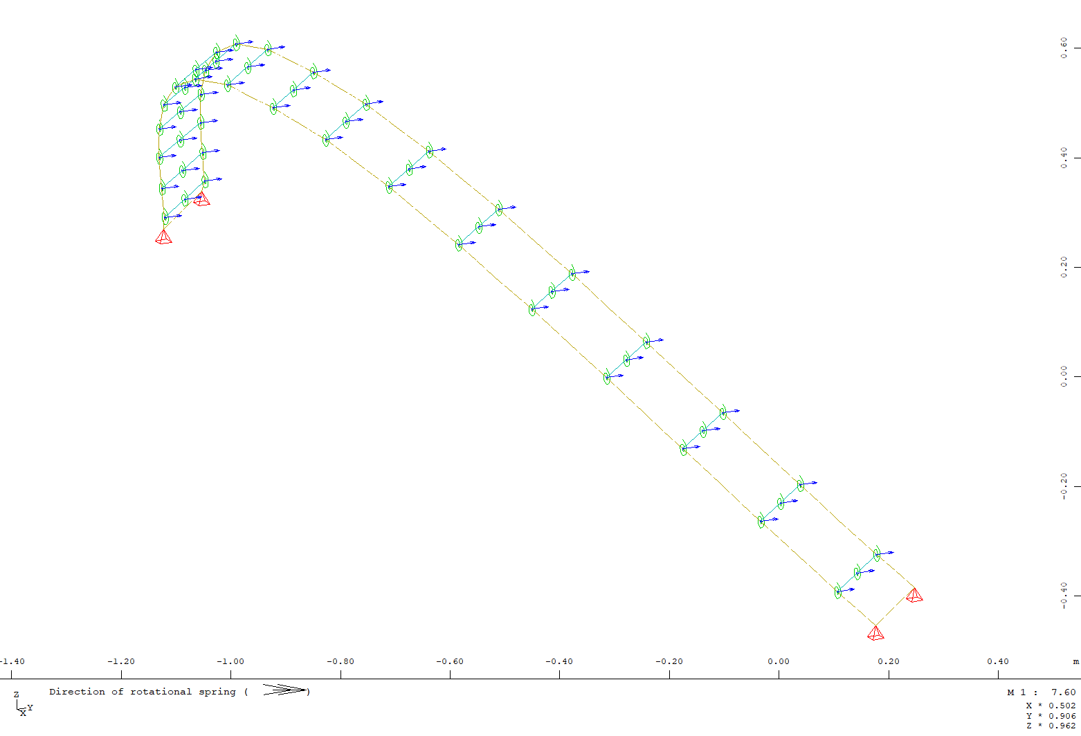
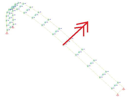
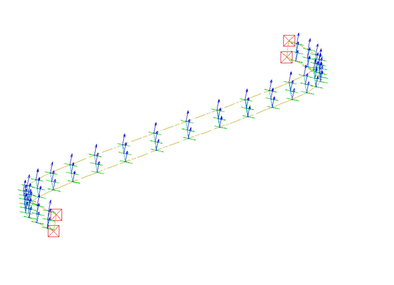
After the bending step, I let the model relax into the correct final form. This is working just fine, as long as I stay in the plane. However, when I bend the strip out of the plane, the rotational springs are still aligned according to the initial direction (see fig. below) and hence allow for less rotation (i.e. they get stiffer).
After the bending step and before the realxation, I run the following module to update the model according to the new geometry
+prog ase urs:16
head Update coordiante system to form found geometry
syst PLC #finalLc STOR yes
ctrl diff
end
however, the springs are still aligned according to the initial geometry. Can someone (possibly @JFH) please help me figure out how I should define the springs, so they follow the deformation and are always aligned along the structural line?
The springs are defined like so.
Sln No -150
SlnS fix 'PXPYPZ' RefT >Sln Ref 156 CD 527.535759
I can;t see what is the shape of deformation you introduced.
Direction of rotational spring should be the same if it is in-plane deformation of system.
Maybe try playing with CTRL SPRI in ASE.
Type CTRL SPRI 8
default is ctrl spri8+4 which keeps direction as in brigde bearings
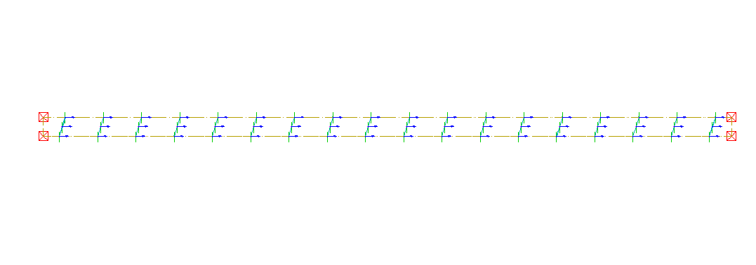
I have got an idea what i s happening.
Since springs in your model have 0.0 length thier direction is not changed becuase second node of spring is not moving, so how could direction of spring change if program does not get information about any displacemnt and rotation between nodes of spring.
The solutiuon maybe defining small difference between copuled SLNs like 1mm, which should allow program to update local coordinate system.
Sln No -150
SlnS fix 'PXPYPZ' RefT >Sln Ref 156 CD 4.852371
and I want them to be oriented parallel to the structural line, how would I do that? After reading the manual, I have the feeling you can only align the spring according to global directions, using DRX, DRY and DRZ.
@mico I was too quick, KR LOCX oriented the springs correctly, but the orientation does not follow the deformation, even if I model a small distance so the nodes are not the same. Even after I’ve updated the model to the deformed geometry like this:
+prog ase
head Update coordiante system to form found geometry
syst PLC #finalLc STOR yes
ctrl diff
end
it doesn’t change, the springs are still oriented as in the beginning.
Ok, I have found with simple two node and one spring example that somehow SYST PLC STOR YES command does not affect spring elements orientation. With beams there is no problem because orientation is not given explicitly but depends on nodes position. There is nothing we can do with this.
However since you are dealing with formfinding like case, in which you need to update spring orientation once I guess (not updating it live during th3 analysis) there is the method, but it is kind of the hard way method.
Do every thing like before with seperating nodes of spring by little distance.
Then you get a model with wrong oriented springs.
Export your model to sofimsha.
Delete all springs in original model.
Copy SPRI definition from exported file to new without explicit orientation definition
Your spring are well-oriented.
-prog sofimsha urs:7
head
syst rest
del spri all
$ lines below copied from NAME_exp.dat file
$SPRI         1      102      105 DX   0.288827   0.957381        0.0 CM  4.80078E-03
SPRI         1      102      105        0.0 CM  4.80078E-03 $ DX DY part needs to be deleted

$ and much more lines...
end