Hi
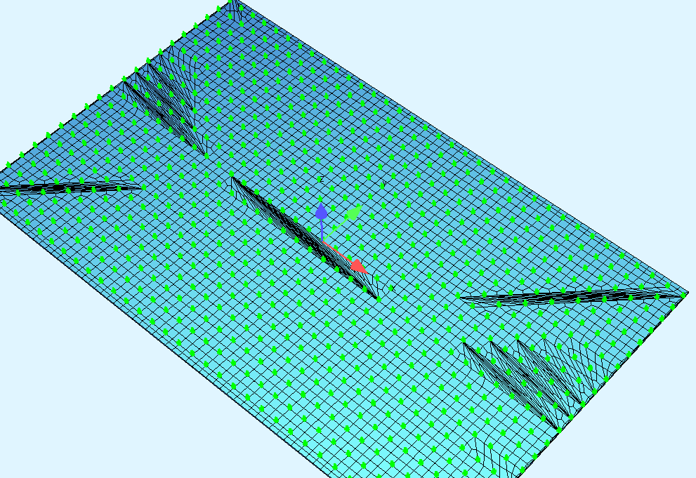
I’m having some issues meshing a large SAR, with inner and outer nodes defined by an input file. The outer nodes represent the geometry of the plate (only four nodes) and the inner nodes represent a pile with a stiffness CP and CQ. Whenever i run the program, the mesh runs into problems in certain areas as shown on the attached figure, and the resulting runtime is almost 3 hours. I have copied the code used below. Is there a way to avoid these meshing errors?
+prog sofimshc urs:15.3
HEAD System
SYST 3D GDIV 100000 GDIR NEGZ
!Outer nodes for plate geometry
SPT 0 X 0 Y 0 Z 0 #Include nodes_geom.dat
SAR 1 MNO 1 GRP 2 NX 0 0 1 T #T
SARB TYPE OUT NA 1 NE 2
SARB TYPE OUT NA 2 NE 4
SARB TYPE OUT NA 4 NE 3
SARB TYPE OUT NA 3 NE 1
GRP NO ‘GR1’ ! Springs
SPT 1000 X 0 Y 0 Z 0 #Include Nodes_exp_A2.dat
$#Include nodes_exp.dat
$#Include nodes_test2.dat
loop#i 735
SPT -(1001+#i) ; SPTS 1001+#i TYPE CZZ CP #ka CQ #kg
endloop
Impossible to say without looking at the geometry in detail (nodes_geom.dat, Nodes_exp_A2.dat, etc)
It seems like you are trying to control the exact location of every single node/element, yet you are using a high level mesh generator (sofimshC)
A wild guess is that:
Nodes are defined twice (once as nodes, once as springs)
Sofimshc merges these two points in 99% of the cases
At a few locations they are defined separately (but close together)
Your mesh control (regular mesh and only quadrilateral elements) makes it hard for sofimshc to find a mesh for these points.
So start by looking at the nodes that were defined in wingraf, make sure you see overlapping numbers, and check for nodes that you don’t think should be there.
I don’t think you can get more help than that unless you post a complete file that can be run.
As far as i can see the nodes are only defined once, which is when the nodes are given the spring support as shown in the code. I do want to upload the teddy files showing the coordinates of the nodes, but i am restricted as a new user.
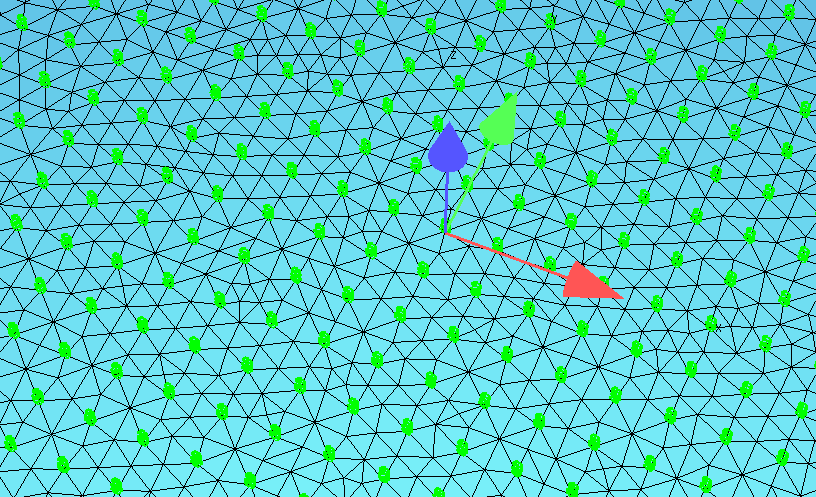
I have updated the mesh restrictions to ctrl mesh 2+96, and the mesh is now run in 2 minutes, instead of 3 hours using quad elements. As far as i can see from the mesh shown below, the nodes are only defined once.
The loads on the plate will consist of ELLA, and hopefully the chosen mesh won’t have restrictions on this.
Ella works better on quadrilateral elements I think.
Unless you have a specific reason for a mesh, I suggest you don’t impose any extra restrictions and start off using the standard settings. Ctrl mesh 2 $ skip the extra specs
Also skip specifying EFACS unless there is a reason (e.g. weird results)