Linear supports on QUAD elements in Teddy

Hello,

I am trying to model a bridge consisting of numerous plates (QUAD elements) with a Teddy script. The model of the bridge is shown below:

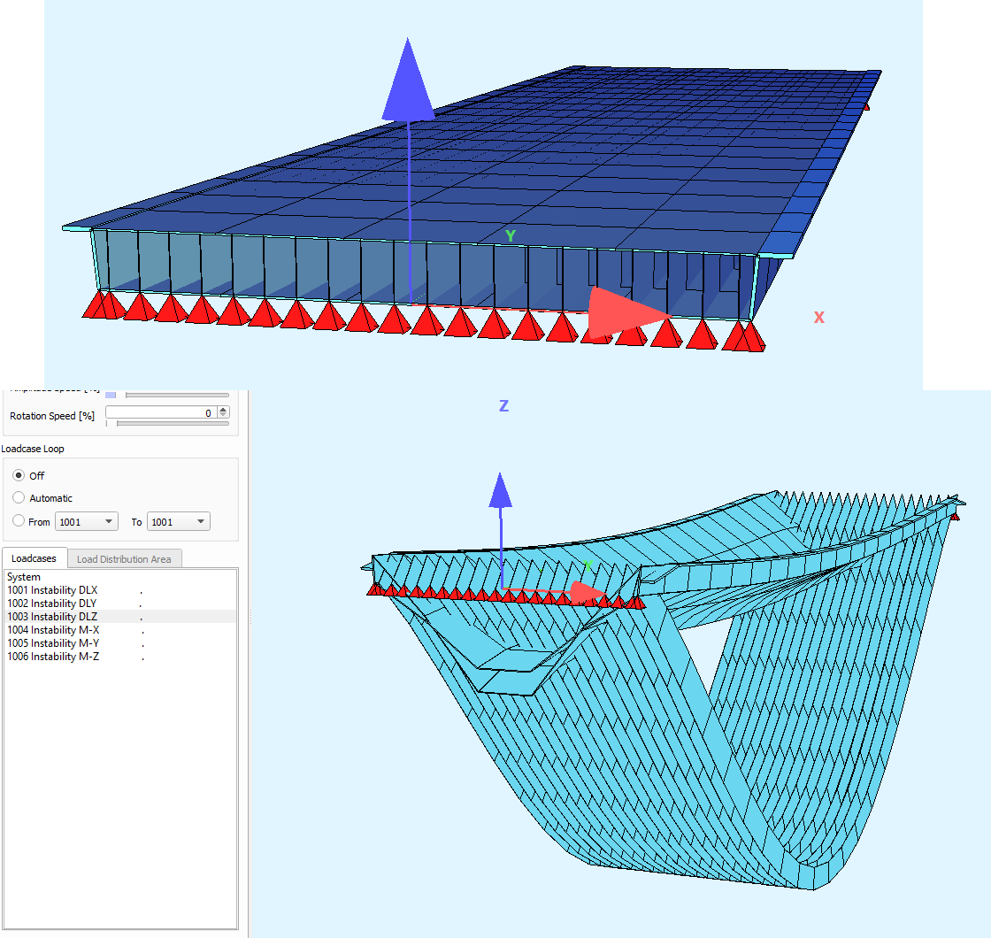
I’d like the edges of the lower plate to be simply supported, but haven’t been able to figure out how. I’ve tried with BOUN, but this only seems to add springs. I read that an EDGE can be created to create boundary conditions, but I couldn’t figure out how to proceed.

So far I tried it by simply imposing supports in the nodes that are used to create the QUAD elements of the vertical plates, but from the figure above it seems that these have no effect on the lower plate (even though this plate also goes through those nodes). I keep getting errors that there are various instabilities, e.g. “Very big rotation in instabilitycheck-LC 1001 at node 216 ! -> WINGRAF”.

Any help will be greatly appreciated!

My scripts can be found below:

+PROG SOFIMSHA urs:5.1 $ Text Interface for Model Creation
HEAD PuursTeddy3
SYST type 3D GDIR NEGZ GDIV 1000

sto#span 16.2 [m] sto#width 4.6 [m]
sto#width_sf 0.2 [m] sto#width_uf #width-2*#width_sf [m]
sto#total_height 0.4 [m], height from top side of upper flange to bottom side of lower flange sto#ctc 0.21 [m]
sto#angle 85 [°] sto#width_lf #width_uf-2*#height/tan(#angle) [m]

$ calculation of number of webs (in steps, because there is no simple round(…) function)
sto#number_of_webs_notrounded #width_lf/#ctc
sto#number_of_webs_roundeddown div(#number_of_webs_notrounded,1)
sto#remainder mod(#number_of_webs_notrounded,1)
if (#remainder < 0.5) ; sto#number_of_webs #number_of_webs_roundeddown ; else ; sto#number_of_webs #number_of_webs_roundeddown+1 ; endif

sto#thickness_web 5 [mm] sto#thickness_uf 12 [mm]
sto#thickness_lf 14 [mm] sto#thickness_sf 31 [mm]
sto#thickness_edge 22 [mm] sto#height #total_height-#thickness_uf/(2*1000)-#thickness_lf/(2*1000) [m] height of wire model (distance between center planes of flanges)
sto#meshsize 0.8

$ creation of all web plates:
loop#i0 #number_of_webs
let#i1 #i0+1
node no 100+#i1 x (#number_of_webs-1)#ctc/2-#i0#ctc y 0 z 0 fix PXPYPZ
node no 200+#i1 x (#number_of_webs-1)#ctc/2-#i0#ctc y 0 z #height
node no 300+#i1 x (#number_of_webs-1)#ctc/2-#i0#ctc y #span z 0 fix PXPYPZ
node no 400+#i1 x (#number_of_webs-1)#ctc/2-#i0#ctc y #span z #height
quad no 1000+#i1 n1 100+#i1 n2 200+#i1 n3 400+#i1 n4 300+#i1 t #thickness_web m #height/#meshsize n #span/#meshsize mno 1
endloop

$ creation of lower flange:
node no 501 x #width_lf/2 y 0 z 0 fix PXPYPZ
node no 502 x -#width_lf/2 y 0 z 0 fix PXPYPZ
node no 503 x -#width_lf/2 y #span z 0 fix PXPYPZ
node no 504 x #width_lf/2 y #span z 0 fix PXPYPZ
grp 1 titl ‘Lower flange’
quad no 1500 n1 501 n2 502 n3 503 n4 504 t #thickness_lf m #width_lf/#meshsize n #span/#meshsize mno 1

$ creation of upper flange:
node no 505 x #width_uf/2 y 0 z #height
node no 506 x -#width_uf/2 y 0 z #height
node no 507 x -#width_uf/2 y #span z #height
node no 508 x #width_uf/2 y #span z #height
grp 2 titl ‘Upper flange’
quad no 1501 n1 505 n2 506 n3 507 n4 508 t #thickness_uf m #width_uf/#meshsize n #span/#meshsize mno 1

$ creation of edges
grp 3 titl ‘Edges’
quad no 1502 n1 501 n2 505 n3 508 n4 504 t #thickness_edge m #height/#meshsize n #span/#meshsize mno 1
quad no 1503 n1 502 n2 506 n3 507 n4 503 t #thickness_edge m #height/#meshsize n #span/#meshsize mno 1

$ creation of horizontal part of side flanges
node no 509 x #width_uf/2 y 0 z #height
node no 510 x #width/2 y 0 z #height
node no 511 x #width/2 y #span z #height
node no 512 x #width_uf/2 y #span z #height
grp 4 titl ‘Side flange 1’
quad no 1504 n1 509 n2 510 n3 511 n4 512 t #thickness_sf m #width_sf/#meshsize n #span/#meshsize mno 1

node no 513 x -#width_uf/2 y 0 z #height
node no 514 x -#width/2 y 0 z #height
node no 515 x -#width/2 y #span z #height
node no 516 x -#width_uf/2 y #span z #height
grp 5 titl ‘Side flange 2’
quad no 1505 n1 513 n2 514 n3 515 n4 516 t #thickness_sf m #width_sf/#meshsize n #span/#meshsize mno 1

END

+PROG SOFILOAD urs:6.1 $ Text Interface for Loads
HEAD Text Interface for Loads

Actions ACT G gamu 1 gamf 1 dead load

$ Loadcases
LC 2 type G TITL ‘dead load’ gamu 1 gamf 1
quad grp 2 type PG P 10

END

  1. The variable #height is undefined (you’ve probably defined in a previous run)
  2. If you want to create a line support you can just use NODE, e.g.:
    NODE FIT 31 41 FIX PZ (see teddy example ./sofimsha/english/sofimsha2_slab.dat
  3. Unless you really want exact control of EVERY node an alternative is using sofimshc, which I find a bit more intuitive.
  4. Looking at your picture the webs are not connected to any of the flanges.
    This is probably since you have created each node twice (one for the web, one for the flange) and they aren’t connected.
    In this case create them once (e.g. for the web) and then reference them when creating the other parts.

Good Luck

May be, the shorter is better (without doubled/extra-nodes, with a fictitous height and some corrections (but not all?).

+PROG SOFIMSHA urs:5.1 $ Text Interface for Model Creation
HEAD PuursTeddy3
SYST type 3D GDIR NEGZ GDIV 1000

sto#height 0.20[m] ????? sto#span 16.2[m]; sto#width 4.6[m] sto#width_sf 0.2[m]; sto#width_uf #width-2*#width_sf[m] sto#total_height 0.4[m] height from top side of upper flange to bottom side of lower flange
sto#ctc 0.21[m]
sto#angle 85[°];sto#width_lf #width_uf-2*#height/tan(#angle)[m]

sto#thickness_web 5[mm]; sto#thickness_uf 12[mm]
sto#thickness_lf 14[mm]; sto#thickness_sf 31[mm]
sto#thickness_edge 22[mm]; sto#height #total_height-#thickness_uf/(21000)-#thickness_lf/(21000)[m] $ height of wire model (distance between center planes of flanges)
sto#meshsize 0.8-0.3

node no 501 x #width_lf/2 y 0 z 0 $fix PXPYPZ
no 502 x -#width_lf/2 y 0 z 0 $fix PXPYPZ
no 503 x -#width_lf/2 y #span z 0 $fix PXPYPZ
no 504 x #width_lf/2 y #span z 0 $fix PXPYPZ
node no 505 x #width_uf/2 y 0 z #height
no 506 x -#width_uf/2 y 0 z #height
no 507 x -#width_uf/2 y #span z #height
no 508 x #width_uf/2 y #span z #height
knot nr 509 x #width_uf/2 y 0 z #height node no 510 x #width/2 y 0 z #height no 511 x #width/2 y #span z #height nr 512 x #width_uf/2 y #span z #height
knot nr 513 x -#width_uf/2 y 0 z #height node no 514 x -#width/2 y 0 z #height no 515 x -#width/2 y #span z #height nr 516 x -#width_uf/2 y #span z #height

grp 1 titl 'Lower flange '; quad no - n1 501 n2 502 n3 503 n4 504 t #thickness_lf m #width_lf/#meshsize n #span/#meshsize mno 1
grp 3 titl ‘Edges’ ; quad no fit n1 501 n2 505 n3 508 n4 504 t #thickness_edge m #height/#meshsize n - mno 1
quad no fit n1 502 n4 506 n3 507 n2 503 t = n #height/#meshsize m - mno = local coordinates ! grp 2 titl 'Upper flange '; quad no fit n1 505 n2 506 n3 507 n4 508 t #thickness_uf m #width_uf/#meshsize n - mno 1 grp 4 titl 'Side flange 1'; quad no fit n1 505 n4 510 n3 511 n2 508 t #thickness_sf n #width_sf/#meshsize m - mno 1 local coordinates !
grp 5 titl ‘Side flange 2’; quad no fit n1 506 n2 514 n3 515 n4 507 t #thickness_sf m #width_sf/#meshsize n - mno 1

node fitl 501 502 fix pp
= 503 504 fix pz $ only vertical (?)
END

This text will be blurred

Codecopy is worse

Blockquote
+PROG SOFIMSHA
HEAD PuursTeddy3
SYST type 3D GDIR NEGZ GDIV 1000
sto#height 0.20[m]
sto#span 16.2[m]; sto#width 4.6[m]
sto#width_sf 0.2[m]; sto#width_uf #width-2*#width_sf[m]
sto#total_height 0.4[m]
sto#ctc 0.21[m]
sto#angle 85[°];sto#width_lf #width_uf-2*#height/tan(#angle)[m]
sto#thickness_web 5[mm]; sto#thickness_uf 12[mm]
sto#thickness_lf 14[mm]; sto#thickness_sf 31[mm]
sto#thickness_edge 22[mm]; sto#height #total_height-#thickness_uf/(21000)-#thickness_lf/(21000)[m]
sto#meshsize 0.8-0.3
node no 501 x #width_lf/2 y 0 z 0
no 502 x -#width_lf/2 y 0 z 0
no 503 x -#width_lf/2 y #span z 0
no 504 x #width_lf/2 y #span z 0
node no 505 x #width_uf/2 y 0 z #height
no 506 x -#width_uf/2 y 0 z #height
no 507 x -#width_uf/2 y #span z #height
no 508 x #width_uf/2 y #span z #height
node no 510 x #width/2 y 0 z #height
no 511 x #width/2 y #span z #height
node no 514 x -#width/2 y 0 z #height
no 515 x -#width/2 y #span z #height
grp 1 titl 'Lower flange '; quad no - n1 501 n2 502 n3 503 n4 504 t #thickness_lf m #width_lf/#meshsize n #span/#meshsize mno 1
grp 3 titl ‘Edges’ ; quad no fit n1 501 n2 505 n3 508 n4 504 t #thickness_edge m #height/#meshsize n - mno 1
quad no fit n1 502 n4 506 n3 507 n2 503 t = n #height/#meshsize m - mno =
grp 2 titl 'Upper flange '; quad no fit n1 505 n2 506 n3 507 n4 508 t #thickness_uf m #width_uf/#meshsize n - mno 1
grp 4 titl ‘Side flange 1’; quad no fit n1 505 n4 510 n3 511 n2 508 t #thickness_sf n #width_sf/#meshsize m - mno 1
grp 5 titl ‘Side flange 2’; quad no fit n1 506 n2 514 n3 515 n4 507 t #thickness_sf m #width_sf/#meshsize n - mno 1
node fitl 501 502 fix pp
= 503 504 fix pz
end

Thank you incredibly much, sfr and ragl! Thanks to your advice and code I was able to solve the problem. I appreciate the quick help from both of you tremendously.

Just a few more concluding notes, just in case anyone with a similar issue would find this topic in the future:
-The height actually was defined in the code, but only after the thicknesses are defined (because the height is calculated from the thicknesses as well as the “#total_height”. The code looked a bit weird after copy pasting it here though.
-The underlying issue with my model was that the nodes of the webs were not nodes of the flanges. I actually didn’t define those nodes a second time for the flanges, each flange was just a single QUAD element with 4 nodes that had nothing to do with the webs. But as I’ve learned now, it’s necessary that the nodes (or the edges of the mesh elements) must coincide in order to make sure the different elements are fixed to each other.

Thank you once again!

Because I had also my problems with the pasting of code into the forum (and the automatic blank trim and other changes by the algorithm):
I found now the solution (but it was not obvious like in the old forum):
You have got insert BBCode-sequenzes:

 testcode

This is a little explained, but not obvious.
Due to the fact that here are often codeexamples:
Dear administration, could you explain this formatting clearly, for instance by display this opportunity ?