The load is defined by p(α,z)=k(α)*k(z)*p0
p0 is a uniform area laod, say 10kPa.
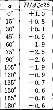
k(α) is defined by a table

k(z)=
How to define such load on curved surface?
The load is defined by p(α,z)=k(α)*k(z)*p0
p0 is a uniform area laod, say 10kPa.
k(α) is defined by a table
How to define such load on curved surface?
Perhaps the attached example helps.
The values are not exactly, but I think they are usable.
2024-Gewolbeflache_Gar_SOF.dat (264.0 KB)
2024-Gewolbeflache_Gar_SOF.gra (1.3 KB)
I mimic the input from you example
| AREA | SAR | NO | (201 216 1) | PROJ | YY | WIDE | 2.5 | TYPE | PZ | $$ |
|---|---|---|---|---|---|---|---|---|---|---|
| P1 | -0.602 | X1 | -2.5 | 0 | 18.5 | $$ | ||||
| P2 | -0.481 | X2 | -2.415 | 0 | 18.5 | $$ | ||||
| P3 | -0.060 | X3 | -2.165 | 0 | 18.5 | $$ | ||||
| P4 | 0.481 | X4 | -1.768 | 0 | 18.5 | $$ | ||||
| P5 | 1.023 | X5 | -1.25 | 0 | 18.5 | $$ | ||||
| P6 | 1.323 | X6 | -0.647 | 0 | 18.5 | |||||
| AREA | SAR | NO | (201 216 1) | PROJ | YY | WIDE | 2.5 | TYPE | CONT | $$ |
| P1 | 1.323 | X1 | 0 | 0 | 18.5 | $$ | ||||
| P2 | 1.023 | X2 | 0.647 | 0 | 18.5 | $$ | ||||
| P3 | 0.481 | X3 | 1.25 | 0 | 18.5 | $$ | ||||
| P4 | 0.361 | X4 | 1.768 | 0 | 18.5 | $$ | ||||
| P5 | 0.301 | X5 | 2.165 | 0 | 18.5 | $$ | ||||
| P6 | 0.301 | X6 | 2.415 | 0 | 18.5 | |||||
| AREA | SAR | NO | (201 216 1) | PROJ | YY | WIDE | 2.5 | TYPE | CONT | $$ |
| P1 | 0.301 | X1 | 2.5 | 0 | 18.5 | |||||
| AREA | SAR | NO | (201 216 1) | PROJ | YY | WIDE | 2.5 | TYPE | CONT | $$ |
| P1 | -0.592 | X1 | -2.5 | 0 | 17.5 | $$ | ||||
| P2 | -0.473 | X2 | -2.415 | 0 | 17.5 | $$ | ||||
| P3 | -0.059 | X3 | -2.165 | 0 | 17.5 | $$ | ||||
| P4 | 0.473 | X4 | -1.768 | 0 | 17.5 | $$ | ||||
| P5 | 1.006 | X5 | -1.25 | 0 | 17.5 | $$ | ||||
| P6 | 1.301 | X6 | -0.647 | 0 | 17.5 | |||||
| AREA | SAR | NO | (201 216 1) | PROJ | YY | WIDE | 2.5 | TYPE | CONT | $$ |
| P1 | 1.301 | X1 | 0 | 0 | 17.5 | $$ | ||||
| P2 | 1.006 | X2 | 0.647 | 0 | 17.5 | $$ | ||||
| P3 | 0.473 | X3 | 1.25 | 0 | 17.5 | $$ | ||||
| P4 | 0.355 | X4 | 1.768 | 0 | 17.5 | $$ | ||||
| P5 | 0.296 | X5 | 2.165 | 0 | 17.5 | $$ | ||||
| P6 | 0.296 | X6 | 2.415 | 0 | 17.5 | |||||
| AREA | SAR | NO | (201 216 1) | PROJ | YY | WIDE | 2.5 | TYPE | CONT | $$ |
| P1 | 0.296 | X1 | 2.5 | 0 | 17.5 |
It shows error
+++++ error no. 2046 in program SL_IA_GL:AREA ; input line: 86
AREA-loading could not be processed, problems with the defined area or least square 3
+++++ error no. 2047 in program SL_IA_GL ; input line: 93
Number of load definition points is restricted to 63
Number of load definition points is 26, it doesn’t exceed 63.
I don’t understand error 2046. The SAR 201~216 are as shown in the image, each is a cylinder surface with 90 degree central angle
Maybe start with one AREA command, add one AREA step by step and see when your error occurs… Also, do the same with your P_i load points within your AREA load. This is really difficult to debug as we don’t see your report and so we can’t find your input line 86 and 93.
Also, keep in mind that the difference between your X values is quite small → smaller than your meshing? Maybe two of your P_i load points land on the same node and then you have an error because of that?
I simplified the geometry with only one SAR: a half cylinder surface with 180 degree central angle
The X coord of the surface is from -2.5m to 2.5m; the y coord is from 0 to 2.5m; the z coord is from 18.5m and 6.5m.
The complete teddy files are attached. Please run “Run.dat”
Sofiload.dat (2.3 KB)
SofimshC.dat (1.7 KB)
Run.dat (84 Bytes)
Aqua.dat (1.1 KB)
In the SOFILOAD module you sent, the last AREA load is not defined with 4 points, so it does not run.
See if this is what you’re looking for. I implemented the formulas you gave in your original post.
+PROG SOFILOAD
HEAD
LET#P0	    10[kN/m2]
LET#alpha   0,15,30,45,60,75,90,105,120,135,150,165,180
LET#K	    1,.8,.1,-.9,-1.9,-2.5,-2.6,-1.9,-.9,-.7,-.6,-.6,-.6
LET#Ka	    'TAB(alpha,K)'
LET#R	    2.5

LC NO 200 TITL Ph
LOOP#Z 12 $ Loop over height from 6.5 to 18.5 m by 1 m
    LET#Kz	    1*((7.0+#Z)/10)**.3
    LOOP#I 12 $ Loop over values of alpha (minus 1)
        LET#J	#I+1
        LET#P1	#Ka(#alpha(#I))*#Kz*#P0
        LET#P2	#Ka(#alpha(#J))*#Kz*#P0
        AREA SAR NO 201 PROJ YY WIDE #R+1 TYPE PZ $$
	    P1  #P1 X1  COS(DEG,#alpha(#I))*#R	Y1 0 Z1 6.5+#Z	$$
	    P2  #P2 X2  COS(DEG,#alpha(#J))*#R			$$
	    P3  #P2 Z3  7.5+#Z					$$
	    P4  #P1 X4  COS(DEG,#alpha(#I))*#R
    ENDLOOP
ENDLOOP

END

+PROG WING
KOPF
LF NR 200
LAST TYP ALLE GTYP EING
BEOB TYP STAN X 0 Y 0 Z 1 ACHS NEGY
LAST TYP ALLE
ENDE

