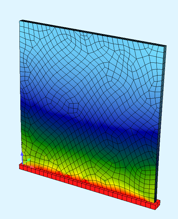
Hello!
I am trying to compare the response of a shell model with an equivalent 3D solid model in SOFiSTiK 2025, but I obtain a very large difference in displacement and I cannot identify the reason.
Shell model
The shell model is created using one structural area:
SAR 1 T 100 MNO 1
The pressure is applied using
AREA SAR 1 TYPE PZ -100
And the maximum displacement is approximately 54 mm.
Solid model
The solid model is created by meshing the same structural area into QUAD elements and then extruding them:
+PROG SOFIMSHC urs:2
head Geometry

syst spac gdiv -1000 gdir negz

ctrl mesh 2+64
ctrl hmin 0.10
ctrl deln 0

spt 1  0 0 0
spt 2  3 0 0
spt 3  3 0 3
spt 4  0 0 3

spt 5  0 0.1 0

sln 1 1 2 fix ppmm
sln 2 2 3
sln 3 3 4
sln 4 4 1
sln 5 1 5  sdiv -5

sar 1 grp 1 mno 1
sarb out 1,2,3,4

end
+PROG SOFIMSHA urs:3
head Generate BRIC Mesh
syst rest
grp 2
bric prop mno 1
extr type sar 1 path sln 5
echo full
end
+PROG SOFILOAD urs:5
head loads
lc 1 type none
area sar 1 type pz -100.0
lc 2 type none
area sar 1 type px -100.0
lc 3 type none
area sar 1 type py -100.0
end
+PROG ASE urs:6
syst prob line
lc 1,2,3
echo elem full
end
Here, the maximum displacement is only about 5 mm.
Questions
-
Is
EXTR TYPE QUAD GRP ...the correct workflow for generating a solid model from a shell? -
Should the original QUAD elements remain active after extrusion?
-
Can the pressure still be applied with
AREA SAR, or should it be applied directly to the generated BRIC boundary faces (GFA)?
Any guidance or example would be greatly appreciated.
Thank you