I’m struggling with understanding the transverse direction of springs.
I have a 2D longitudinal model, made in a 3D system (in order to use axes).
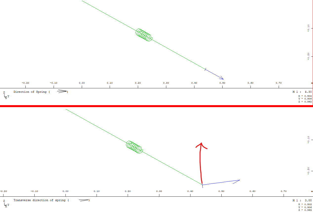
When I define a spring with the main direction along the longitudinal axis, I want the transverse direction to be in the vertical direction.
However, when defining the spring, the transverse is in the perpendicular horizontal direction to the main direction, and I see no means of rotating the spring.
Please see the attached snippet below with the wished transverse direction shown with a red arrow.
+Prog SOFIMSHC urs:2 $ Geometry
SYST 3D GDIV 100 GDIR NEGZ
ctrl mesh 1
SPT 1 X 0 Y 0 Z 0
SPT 2 X 1 Y 0 Z 0
spts no 3 ref 1 CQ 10 CP 100 CRAC 0.0 grp 1 type C DX 1 DY 0 DZ 0
end
as you can see in the manual, the transverse spring direction is a plane perpendicular to the axial direction:
The first parameter CA describes an axial stiffness along the principal direction of the spring. The second parameter CQ describes a stiffness component acting in the whole plane perpendicular to the axial direction.
In your case you need to define 2 single springs, both with a value CP:
spts … CP 100 DX 1 DY 0 DZ 0
spts … CP 10 DX 0 DY 0 DZ 1
Thank you very much for your reply, I had a feeling that was the issue as well.
In your example, would there be any difference in writing:
spts … CP 100 CQ 10 DX 1 DY 0 DZ 0
instead of:
spts … CP 100 DX 1 DY 0 DZ 0
spts … CP 10 DX 0 DY 0 DZ 1
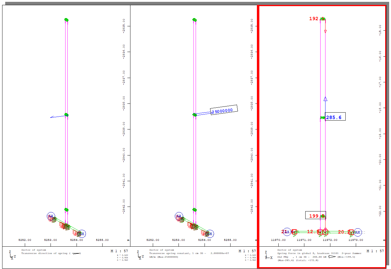
The reason I’m asking is that in my main model which I’ve tried to summarize in the previous model, I see a vertical spring force in springs which have no transverse stiffness assigned. Please see the figure below: