Hello there,
i am trying to create an frame corner with recessed bar and flange. I have defined the cross section with this
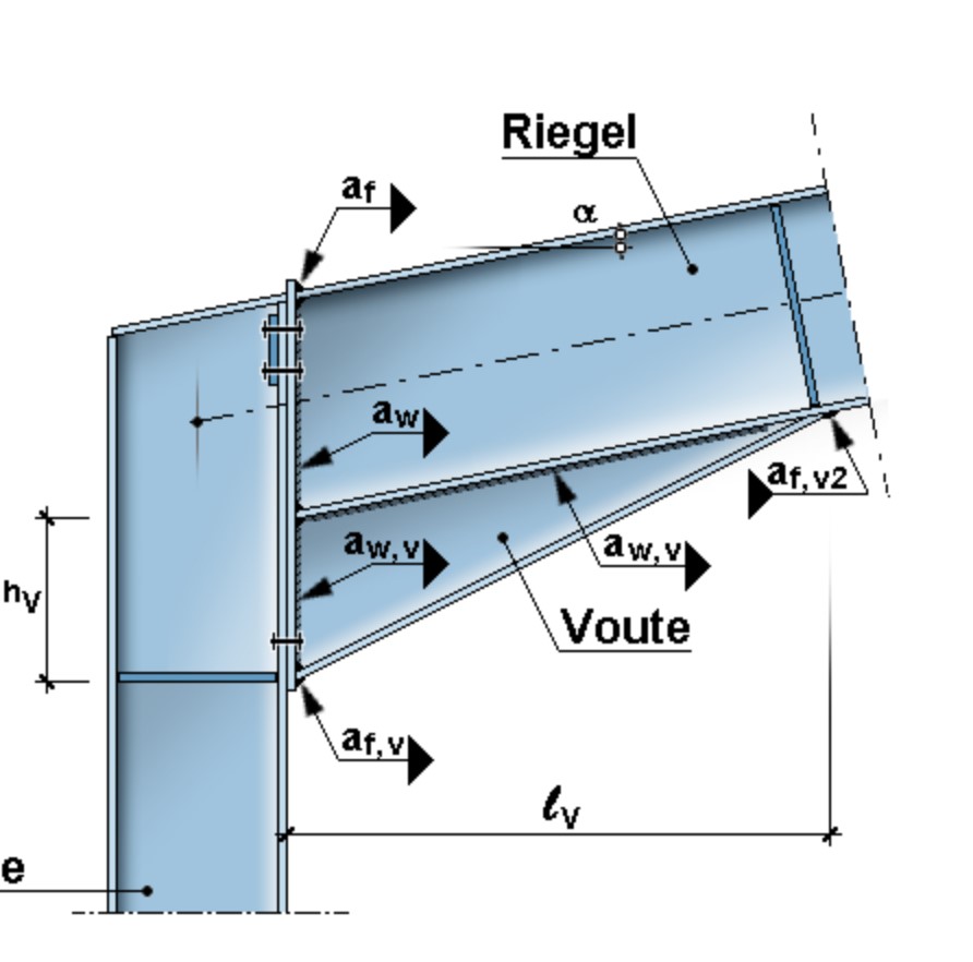
’ $ Voute mit vollständigem I-Profil und untergesetztem Steg und Flansch: ******************************
$ parameter definition of the bottom web and flange.
let#s 10 $Dicke Zustatzstegblech
let#t 15 $Dicke Zusatzflansch
let#b 200 $Breite des Zusatzflansches
let#hv 510 $Höhe UK Träger bis UK Zusatzflansch außen
let#hp 300 $Höhe des Profils $ IPE 300 = 300mm Höhe
let#tp 13.5 $Dicke des profilflansches
let#a 6.0 $Schweißnahtdicken (Summe der Kehlnähte)
let#hv2 20 $ Höhe UK Träger bis UK Zusatzflansch Vouten innen
$Voute außen
QNR 5 MNR 1
prof 1 ipe 300 dtyp d
blec 1 0.00 #hp/2 0.00 #hp/2+#hv-#t #s laga 0 lage 0
blec 2 #b/2 #hp/2+#hv-#t/2 0.00 #hp/2+#hv-#t/2 #t laga free lage 0
blec 3 -#b/2 #hp/2+#hv-#t/2 0.00 #hp/2+#hv-#t/2 #t laga free lage 0
lnah 1 0.00 #hp/2-#tp/2 0.00 #hp/2 #a
lnah 2 0.00 #hp/2+#hv-#t/2 0.00 #hp/2+#hv-#t #a
$Voute innen
QNR 11 MNR 1
prof 1 ipe 300 dtyp d
blec 1 0.00 #hp/2 0.00 #hp/2+#hv2-#t #s laga 0 lage 0
blec 2 #b/2 #hp/2+#hv2-#t/2 0.00 #hp/2+#hv2-#t/2 #t laga free lage 0
blec 3 -#b/2 #hp/2+#hv2-#t/2 0.00 #hp/2+#hv2-#t/2 #t laga free lage 0
lnah 1 0.00 #hp/2-#tp/2 0.00 #hp/2 #a
lnah 2 0.00 #hp/2+#hv2-#t/2 0.00 #hp/2+#hv2-#t #a
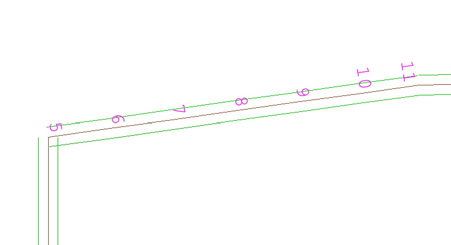
INTE (6 10 1) 5 11 S (1/6 1/6) ' $ interpolation between CS 5 and 11 in every 1/6th distance.
This composite CS sections of an IPE300 Profile and a web and flange welded to it at the bottom. The web’s height keeps on increasing as one moves towards the frame corner.
The problem i am having is since this is an interpolated cross section, the program is connecting the geometric centre line of this composite interpolating cross section with the adjoining members. The geometric centre line by virtue of interpolation is slanted. My goal is that the axis of connection remains along the centre of the IPE profile and the geometric centre line of the composite CS. How could i do it? Thanks for the help.
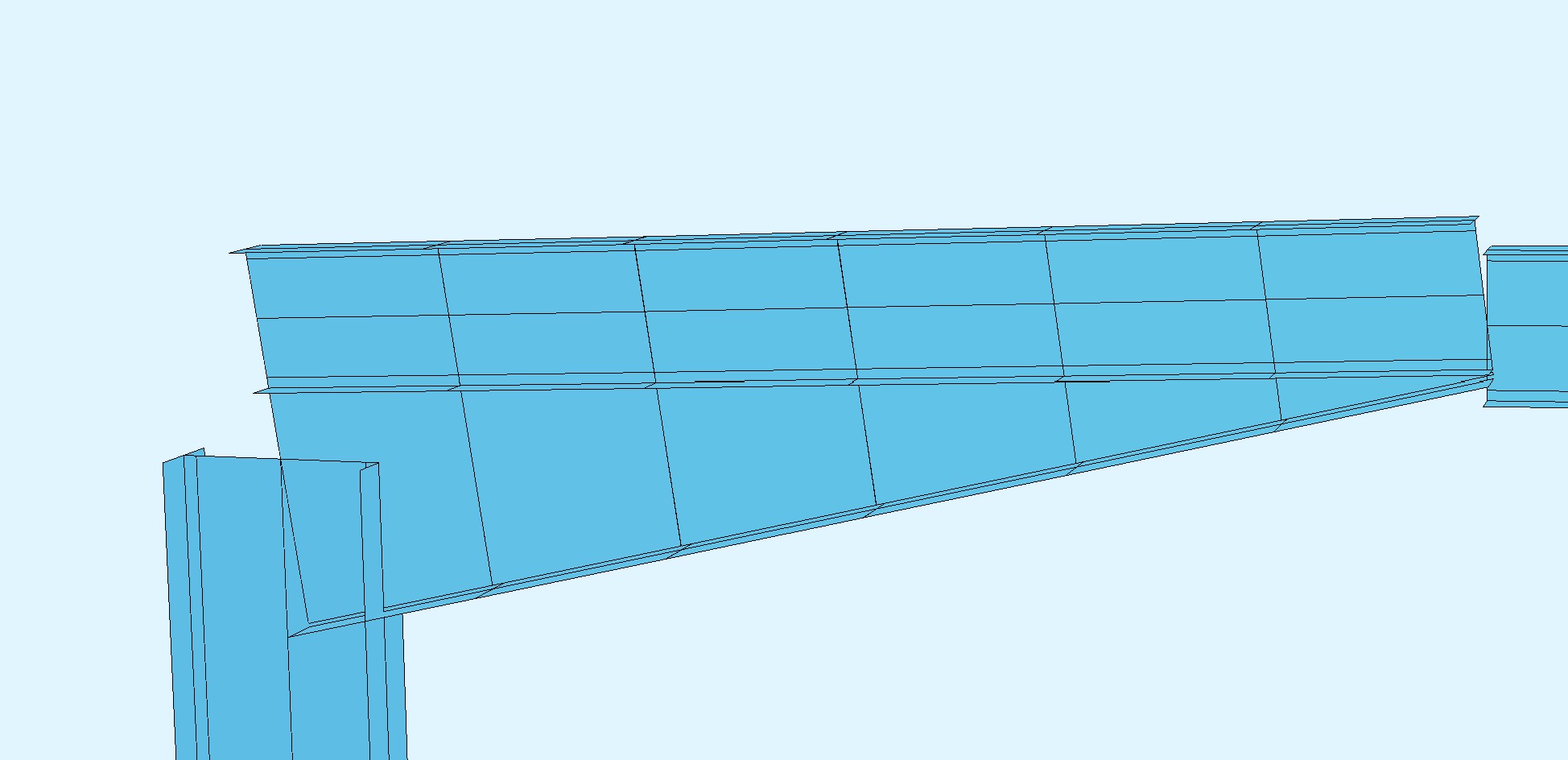
This is how it looks currently.