A 10m x 10m flat shell, the thickness is 0.05m, the E modulus is 2.1e7 MPa, the shear modulus is 80770 MPa. A uniform load of 1kPa is applied download on the shell.
There are two models
- The 4 corners of the shell are simply supported.
- 4 beams are under the shell edges, the ends of the beam are simply supported., while 4 very stiff springs connect the support and the corner of the shell.
You would expect that the displacement of the shell in model 1 and model 2 should be very close.
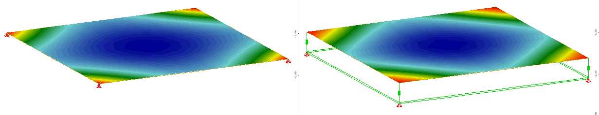
The image below show the displacement contour of model 1(left) and model 2 (right) in Sap2000. The max disp in model 1 is 106.8 mm, while that in model 2 is 107.1 mm, they are very close.
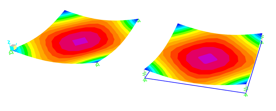
The image below show the displacement contour of model 1(left) and model 2 (right) in Sofistik. The max disp in model 1 is 105 mm, which is close to that in Sap2000, while that in model 2 is only 55.6 mm.
As you can see, the 4 beams in Model 2 should have no effect on the result.
Then why the results in Sofistik are different?
The Teddy code is uploaded, please download it and change Sofistik1.dat to Sofistik1.zip, then unzip it.
Sofistik1.dat (1.9 KB)
Please run Model 1.dat or Model 2.dat to get result.