Suggestion: Tendon in Solid

The “Tendon” module only supports tendon in beam and shell/plate.
Other bridge professional softwares like Midas FEA, CSiBidge, Lusas, Brigade, etc support tendon in solid feature.

Is it possible to add feature “Tendon in Solid” in the future version?

You can use cable elemtens to describe tendon in brics
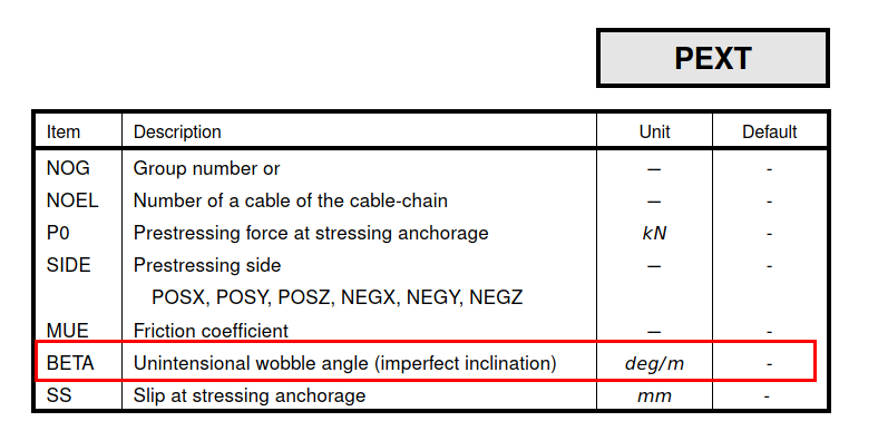
With PEXT in ase it account force losses
Brics are meant for sophisticated checks so if you do those you can handle pt in it
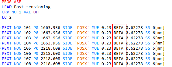
@ mico

I model the cable and solid in SofimshA

Then I run ASE

PROG ASE
HEAD Post-tensioning
GRP NO 1 VAL OFF
LC 2
PEXT NOG 101 P0 1663.956 SIDE ‘POSX’ MUE 0.23 BETA 0.62278 SS 6[mm]
PEXT NOG 102 P0 1663.956 SIDE ‘POSX’ MUE 0.23 BETA 0.62278 SS 6[mm]
PEXT NOG 103 P0 1663.956 SIDE ‘POSX’ MUE 0.23 BETA 0.62278 SS 6[mm]
PEXT NOG 104 P0 1663.956 SIDE ‘POSX’ MUE 0.23 BETA 0.62278 SS 6[mm]
PEXT NOG 105 P0 2218.608 SIDE ‘POSX’ MUE 0.23 BETA 0.62278 SS 6[mm]
PEXT NOG 106 P0 2218.608 SIDE ‘POSX’ MUE 0.23 BETA 0.62278 SS 6[mm]
PEXT NOG 107 P0 2218.608 SIDE ‘POSX’ MUE 0.23 BETA 0.62278 SS 6[mm]
PEXT NOG 108 P0 2218.608 SIDE ‘POSX’ MUE 0.23 BETA 0.62278 SS 6[mm]
PEXT NOG 109 P0 924.42 SIDE ‘POSX’ MUE 0.23 BETA 0.62278 SS 6[mm]
PEXT NOG 110 P0 924.42 SIDE ‘POSX’ MUE 0.23 BETA 0.62278 SS 6[mm]
PEXT NOG 111 P0 924.42 SIDE ‘POSX’ MUE 0.23 BETA 0.62278 SS 6[mm]
PEXT NOG 112 P0 924.42 SIDE ‘POSX’ MUE 0.23 BETA 0.62278 SS 6[mm]
PEXT NOG 113 P0 924.42 SIDE ‘POSX’ MUE 0.23 BETA 0.62278 SS 6[mm]
PEXT NOG 201 P0 1663.956 SIDE ‘POSX’ MUE 0.23 BETA 0.62278 SS 6[mm]
PEXT NOG 202 P0 1663.956 SIDE ‘POSX’ MUE 0.23 BETA 0.62278 SS 6[mm]
PEXT NOG 203 P0 1663.956 SIDE ‘POSX’ MUE 0.23 BETA 0.62278 SS 6[mm]
PEXT NOG 204 P0 1663.956 SIDE ‘POSX’ MUE 0.23 BETA 0.62278 SS 6[mm]
PEXT NOG 205 P0 2218.608 SIDE ‘POSX’ MUE 0.23 BETA 0.62278 SS 6[mm]
PEXT NOG 206 P0 2218.608 SIDE ‘POSX’ MUE 0.23 BETA 0.62278 SS 6[mm]
PEXT NOG 207 P0 2218.608 SIDE ‘POSX’ MUE 0.23 BETA 0.62278 SS 6[mm]
PEXT NOG 208 P0 2218.608 SIDE ‘POSX’ MUE 0.23 BETA 0.62278 SS 6[mm]
PEXT NOG 209 P0 924.42 SIDE ‘POSX’ MUE 0.23 BETA 0.62278 SS 6[mm]
PEXT NOG 210 P0 924.42 SIDE ‘POSX’ MUE 0.23 BETA 0.62278 SS 6[mm]
PEXT NOG 211 P0 924.42 SIDE ‘POSX’ MUE 0.23 BETA 0.62278 SS 6[mm]
PEXT NOG 212 P0 924.42 SIDE ‘POSX’ MUE 0.23 BETA 0.62278 SS 6[mm]
PEXT NOG 213 P0 924.42 SIDE ‘POSX’ MUE 0.23 BETA 0.62278 SS 6[mm]
PEXT NOG 114 P0 924.42 SIDE ‘POSX’ MUE 0.23 BETA 0.62278 SS 6[mm]
END

It shows errors

+++++ error no. 12110 ; input line: 8
Improper name of item (or literal not allowed) at position 6
Hint: This may be caused by a change of the structure of this record
please compare the current manual/status line with your input data.
The use of items especially for later positions may avoid those problems
+++++ error no. 12108 ; input line: 8
Item at position 7 multiple defined
If a literal item to be specified is identical to the name of an item,
please quote the Literal with apostrophes

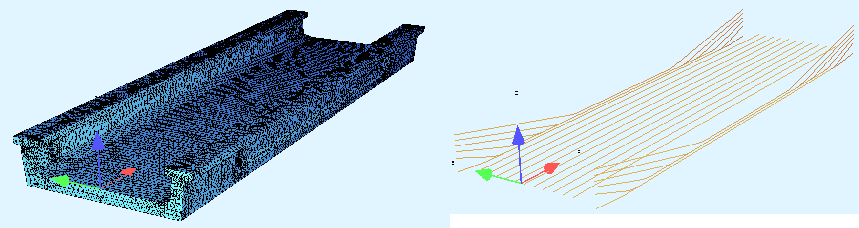
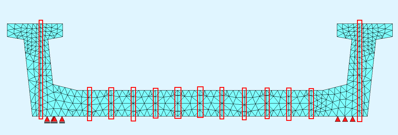
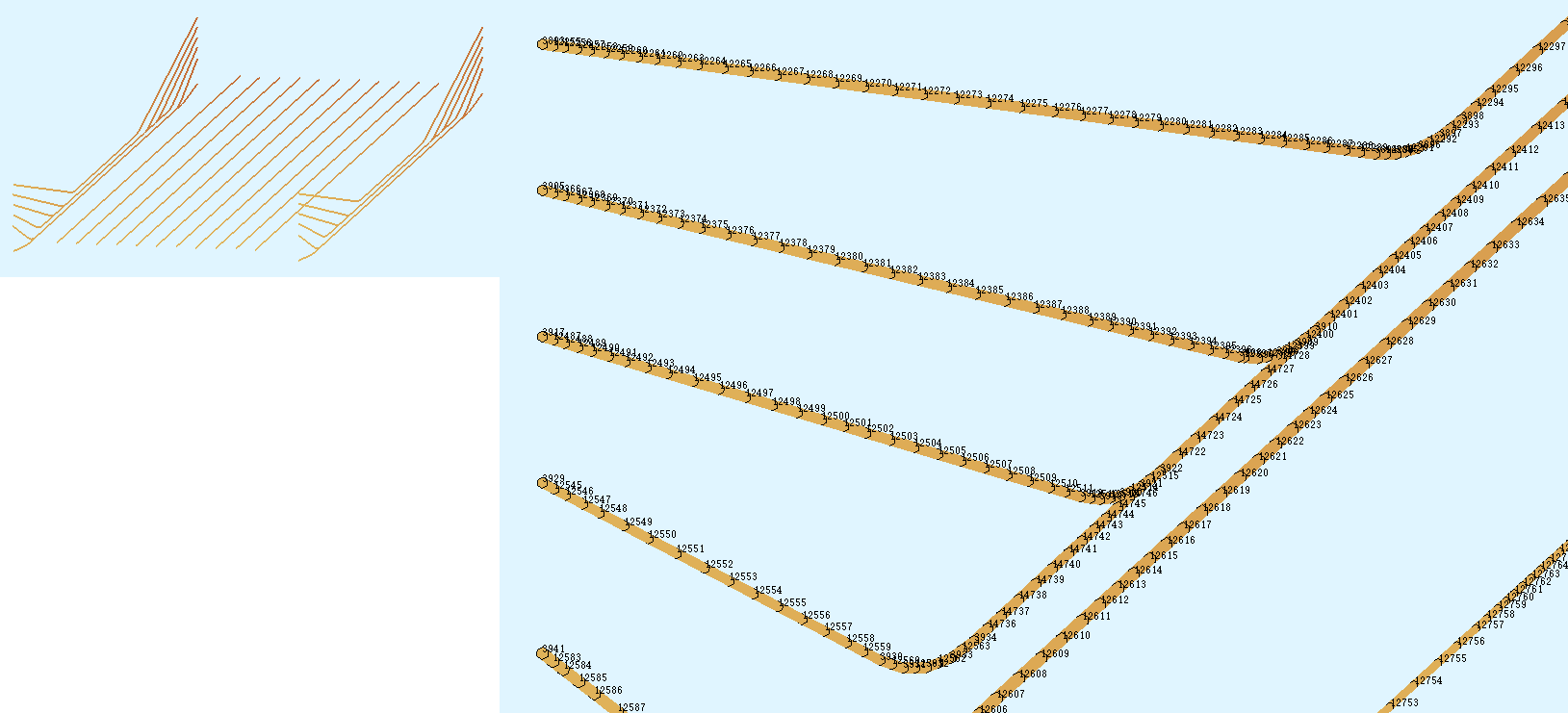
You have to descipe cable elements on the same nodes as bric elements.
It seems there are three planes on which cables are, so if you use sofimshc SVO add sar’s in those plane to define volumes.

  1. I define solid and cables in two SofimshA files. Do you mean I have to merge these two files?

  2. I use
    PROG SofimshA urs:3
    HEAD
    SYST REST

    GRP 10
    BRIC PROP MNR 1
    UMSH TYPE
    TET
    UBND TYPE SEL N1
    OUT QGRP 1
    to define solid, is it OK? Do I have to use SVO instead?

Cables should be on boundary of bric - ubnd

Thank you for the suggestions, I still have two questions:

  1. I can break the cable into many pieces and get the coordinates of the nodes on the cable. How can I make sure these nodes are the nodes on the brick elements? The only possible option is "X Y Z“ but they are for COOR type.

  2. Even if the cable’s nodes are on the brick elements, when I define the cable, I still don’t know the nodes ID since they are created automatically. Can I use my own nodes IDs? Eg. The (0,0,0) is the node coordinate of the cable. The auto-generated ID is 1001 in bric element. Since I don’t know this ID, I use 101 for the node to define my cable.

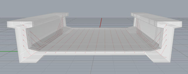
You dont need to know any nodes
Just define cables on an area which is boundary of bric
Try with one cable on outer surface of your model then try to divide volume to achive mid-surfaces on what you can define cables

“Just define cables on an area which is boundary of bric”——The cables are all inside the solid, not on the outer boundary of the solid.

I don’t understand this “divide volume to achive mid-surfaces on what you can define cables”.

I know cable are inside and thats why you have to make 3-4 solids instead of one. So cables will be on boundaries of new solids

How to define these cables then? Or they will be created automatically?
I’m confused.

prog aqua urs:1
head
norm en 1992-2004
conc no 2 c 30
stee no 1 s 500b
prof 1 type bar 50

end

+prog sofimshc urs:2
head
syst spac gdiv 10000
ctrl mesh 2

$ cable trajectory
sln sno 1 styp 'ce' xflg -; slnb x1 0 x2 2.5 z1 -1 z2 -0.2
sln sno 1 styp 'ce' xflg -; slnb x1 2.5 x2 5.0 z1 -0.2 z2 -1

$ bric faces
sar grp 1
sarb out;  slnb x1 0 x2 5 y1 -2 y2 -2 z1 0 z2 0
sarb out;  slnb x1 0 x2 5 y1  0 y2  0 z1 0 z2 0
sarb out;  slnb x1 5 x2 5 y1  0 y2  -2 z1 0 z2 0
sarb out;  slnb x1 0 x2 0 y1  0 y2  -2 z1 0 z2 0
sar grp 1
sarb out;  slnb x1 0 x2 5 y1 -2 y2 -2 z1 -2 z2 -2
sarb out;  slnb x1 0 x2 5 y1  0 y2  0 z1 -2 z2 -2
sarb out;  slnb x1 5 x2 5 y1  0 y2  -2 z1 -2 z2 -2
sarb out;  slnb x1 0 x2 0 y1  0 y2  -2 z1 -2 z2 -2
sar grp 1
sarb out;  slnb x1 0 x2 0 y1 -2 y2 -2 z1 0 z2 -2
sarb out;  slnb x1 0 x2 0 y1  0 y2  0 z1 0 z2 -2
sarb out;  slnb x1 0 x2 0 y1  0 y2  -2 z1 0 z2 0
sarb out;  slnb x1 0 x2 0 y1  0 y2  -2 z1 -2 z2 -2
sar grp 1
sarb out;  slnb x1 5 x2 5 y1 -2 y2 -2 z1 0 z2 -2
sarb out;  slnb x1 5 x2 5 y1  0 y2  0 z1 0 z2 -2
sarb out;  slnb x1 5 x2 5 y1  0 y2  -2 z1 0 z2 0
sarb out;  slnb x1 5 x2 5 y1  0 y2  -2 z1 -2 z2 -2
sar grp 1
sarb out;  slnb x1 0 x2 0 y1  0 y2 0 z1 0 z2 -2
sarb out;  slnb x1 5 x2 5 y1  0 y2  0 z1 0 z2 -2
sarb out;  slnb x1 0 x2 5 y1  0 y2 0 z1 0 z2 0
sarb out;  slnb x1 0 x2 5 y1  0 y2 0 z1 -2 z2 -2
sar grp 1
sarb out;  slnb x1 0 x2 0 y1  -2 y2 -2 z1 0 z2 -2
sarb out;  slnb x1 5 x2 5 y1  -2 y2 -2 z1 0 z2 -2
sarb out;  slnb x1 0 x2 5 y1  -2 y2 -2 z1 0 z2 0
sarb out;  slnb x1 0 x2 5 y1  -2 y2 -2 z1 -2 z2 -2

sar grp 2
sarb out;  slnb x1 0 x2 5 y1 +2 y2 +2 z1 0 z2 0
sarb out;  slnb x1 0 x2 5 y1  0 y2  0 z1 0 z2 0
sarb out;  slnb x1 5 x2 5 y1  0 y2  +2 z1 0 z2 0
sarb out;  slnb x1 0 x2 0 y1  0 y2  +2 z1 0 z2 0
sar grp 2
sarb out;  slnb x1 0 x2 5 y1 +2 y2 +2 z1 -2 z2 -2
sarb out;  slnb x1 0 x2 5 y1  0 y2  0 z1 -2 z2 -2
sarb out;  slnb x1 5 x2 5 y1  0 y2  +2 z1 -2 z2 -2
sarb out;  slnb x1 0 x2 0 y1  0 y2  +2 z1 -2 z2 -2
sar grp 2
sarb out;  slnb x1 0 x2 0 y1 +2 y2 +2 z1 0 z2 -2
sarb out;  slnb x1 0 x2 0 y1  0 y2  0 z1 0 z2 -2
sarb out;  slnb x1 0 x2 0 y1  0 y2  +2 z1 0 z2 0
sarb out;  slnb x1 0 x2 0 y1  0 y2  +2 z1 -2 z2 -2
sar grp 2
sarb out;  slnb x1 5 x2 5 y1 +2 y2 +2 z1 0 z2 -2
sarb out;  slnb x1 5 x2 5 y1  0 y2  0 z1 0 z2 -2
sarb out;  slnb x1 5 x2 5 y1  0 y2  +2 z1 0 z2 0
sarb out;  slnb x1 5 x2 5 y1  0 y2  +2 z1 -2 z2 -2
sar grp 2
sarb out;  slnb x1 0 x2 0 y1  0 y2 0 z1 0 z2 -2
sarb out;  slnb x1 5 x2 5 y1  0 y2  0 z1 0 z2 -2
sarb out;  slnb x1 0 x2 5 y1  0 y2 0 z1 0 z2 0
sarb out;  slnb x1 0 x2 5 y1  0 y2 0 z1 -2 z2 -2
sar grp 2
sarb out;  slnb x1 0 x2 0 y1  +2 y2 +2 z1 0 z2 -2
sarb out;  slnb x1 5 x2 5 y1  +2 y2 +2 z1 0 z2 -2
sarb out;  slnb x1 0 x2 5 y1  +2 y2 +2 z1 0 z2 0
sarb out;  slnb x1 0 x2 5 y1  +2 y2 +2 z1 -2 z2 -2


end 
PROG SofimshA 
HEAD
SYST REST

GRP 10
BRIC PROP MNR 2
UMSH TYPE
TET
UBND TYPE SEL N1
OUT QGRP 1

GRP 10
BRIC PROP MNR 2
UMSH TYPE
TET
UBND TYPE SEL N1
OUT QGRP 2
1 Like

I cut the solid by several planes (in red lines) on which the cables are located. Then defined cables

The very dense node IDs means the nodes of the cable are on the bric elements

But the ASE run still has errors

+++++ error no. 12110 ; input line: 8
Improper name of item (or literal not allowed) at position 6
Hint: This may be caused by a change of the structure of this record
please compare the current manual/status line with your input data.
The use of items especially for later positions may avoid those problems
+++++ error no. 12108 ; input line: 8
Item at position 7 multiple defined
If a literal item to be specified is identical to the name of an item,
please quote the Literal with apostrophes

Teddy files are attached.

0. include.dat (145 Bytes)
Aqua.dat (550 Bytes)
ASE.dat (1.9 KB)
SofimshA-Solid.dat (734 Bytes)
SofimshC.dat (450.8 KB)

@mico
I notice that the keywords such as “PEXT”, “NOG”, “MUE” are highlighted, except “BETA”, is that the culprit?

Conclusion

  1. The “BETA” is the culprit. After deleting “BETA 0.62278” the ASE runs without error.
  2. The “SS 6[mm]” should be “SS 6”.

Beta is wooble factor so it is for internal cables and pext intention are extrrnal ones

But in the end does it work?

If it’s for external cable,why it has beta

I made a simple model and Pext works without BETA, which I want to include in the analysis.

tet_hanging_nodes - PEXT.dat (1.7 KB)