Sofistik 2025-3
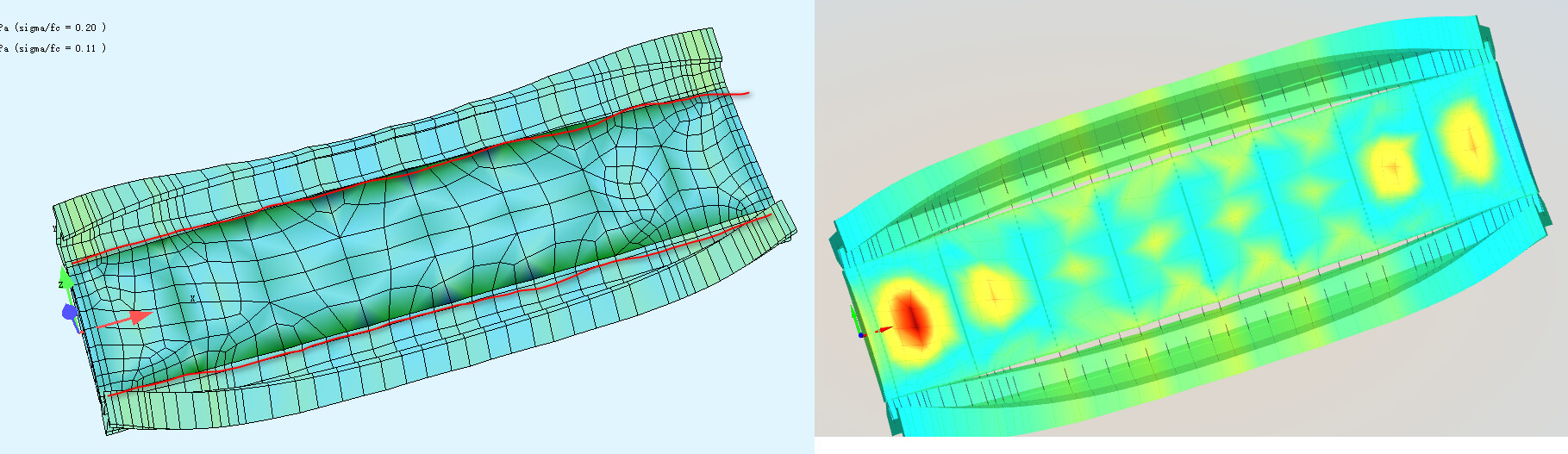
The red lines in the left image represent the borders of beam and surface, and you can see they are connected when structure deformed. But they are detached in Sofistik Viewer.
Sofistik 2025-3
The red lines in the left image represent the borders of beam and surface, and you can see they are connected when structure deformed. But they are detached in Sofistik Viewer.
Please check the behaviour with Version 2025 SP4.
If this does not solve the problem please upload this little system with this shown load case.
Regards,
Jost
Yes, the 2025-4 has the same issue.
Plese run “0. include.dat” and take a look at dispalcement at Loadcase 4010.
0. include.dat (113 Bytes)
1. VAR.dat (377 Bytes)
Aqua (2).dat (3.7 KB)
CSM.dat (1.1 KB)
SofimshC.dat (18.4 KB)
I see, you are right. This is a visualisation problem of the Viewer. We will check this, thank you for this hint.
Best regards,
Jost
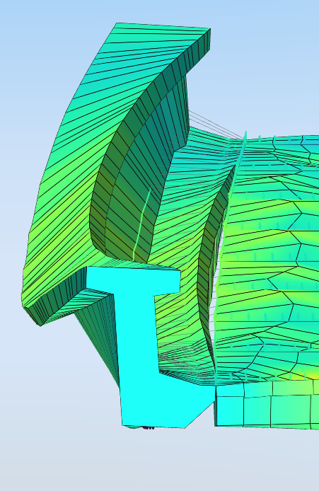
01a shows that, due to torsion, the centroid of the main girder shifts significantly to the left at midspan. Consequently, the lower right flange, which is actually connected to the deck, must also be displaced to the left. In reality, however, the girder experiences transverse stress and deformation, which is captured by the Animator but not by the Viewer. As a result, a gap appears in the viewer.
Here you find another explanation why results from Animator are not correct:
netsonic_Sofistik
“the girder experiences transverse stress and deformation, which is captured by the Animator but not by the Viewer. As a result, a gap appears in the viewer.”
This is what I expected, the deformation in the Animator is correct while that in the viewer is wrong.
But in the linked explanation, the conlusion is
The deformed shape in the Viewer is the expected results.
Does it mean the deformation in the viewer is correct?
The system provides displacements and rotations of the nodes. These are transformed onto the beam axis (centroidal axis), and the resulting image is derived from that. However, since transverse stresses on the beam cross-sections are not considered in this transformation, gaps inevitably appear in locations where they are not expected.
So: Yes, the viewer does display the ‘correct’ deformations.
The fact that no gap appears in the Animator view is probably due to the gap having been ‘programmed away’ at some point for certain boundary conditions. However, for other boundary conditions (types of modeling) that should actually produce the same result, such gaps do appear even in the Animator.