Hello every one
I hope every one is fine
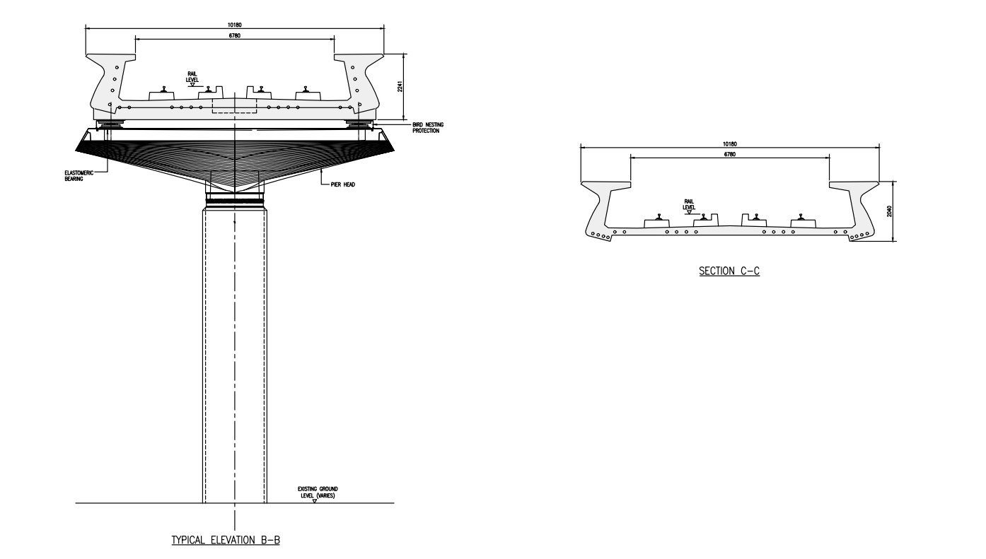
In this bridge as attached in (Fig 1) the cross section of the bridge is precast prestressed U-Girder as shown
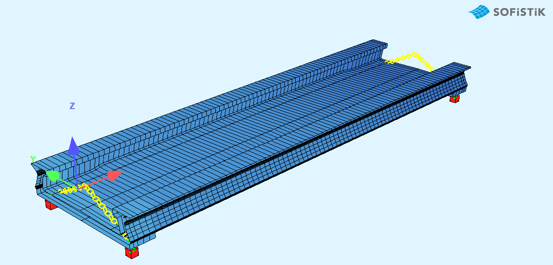
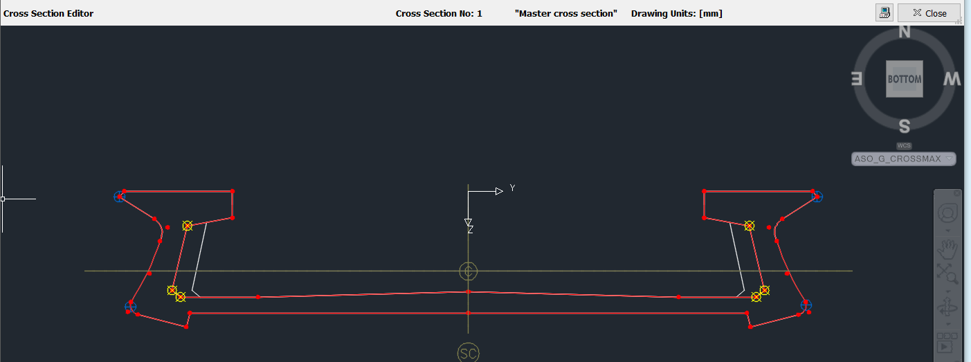
Firstly I use the beam spine model to model this cross section as shown in (Fig 2 and Fig 3) but I want to model this cross section with shell element
How I can draw this cross section with its curvature’s in SOFIPLUS -X with shell element instead of beam element ?
For this geometry I would recommend to model slab between girders as shell elements, but girders itself as beam elements.
In sofiplus you have to draw girders as SLN as you have done prevously but twice and then between those lines define Structural Area describing the slab.
Hi mico
Thank you for your reply
It is possible to model the full cross section (girders and connected slab) as shell element ?
I want to model the full cross section as a shell element to capture to warping, distortion and shear lag effects of this cross section
If I Modell the side beam as a beam element and the connected slab with shell element, This can capturer warping, distortion and shear lag effects of this cross section ?
Yes it will capture those effects
Ok mico
Thank you
I will modal this cross section as you recommended
but for my information only it is possible to the full cross section (girders and connected slab) as shell element in SOFIPLUS ?
sorry mico
Another question
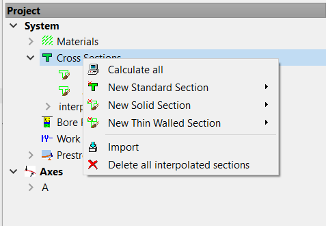
if I modal the side beams as a beam element you recommended to use a solid section or thin walled section as shown in the following figure
Hello mico
Good morning
I hope you are fine
can you help me please with the last 2 replies in this post about (modelling the full cross section as a shell element and using a solid or thin walled section for cross section
I would go for solid with this shape