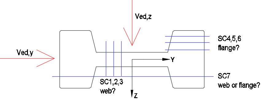
How to correctly set the shear cuts so that the force Ved,y is only supported by the web, and the force Ved,z by the flanges. Sections 1,2,3 (with web description) are set so that reinforcement is obtained in the web, and sections 4,5,6 (with flange description) so that reinforcement is obtained in the flange. I am curious what is obtained in the case of section 7?
In general, is the thinking good and how should the sections be set to obtain correct values of shear reinforcement?
I also read the explanations in the Aqua manual, but it’s not entirely clear to me.
I’m sorry, but I still don’t understand. Could you show, for this type of cross-section, how the shear cuts should be set and which type to use in order to obtain the correct reinforcement in the web and in the flange?
Thank you in advance!
The correct arrangement of shear cuts depends, among other things, on the applied loads as well as the existing reinforcement and prestressing tendons. Without these boundary conditions I therefore cannot give definitive recommendations. The following notes should, however, be useful:
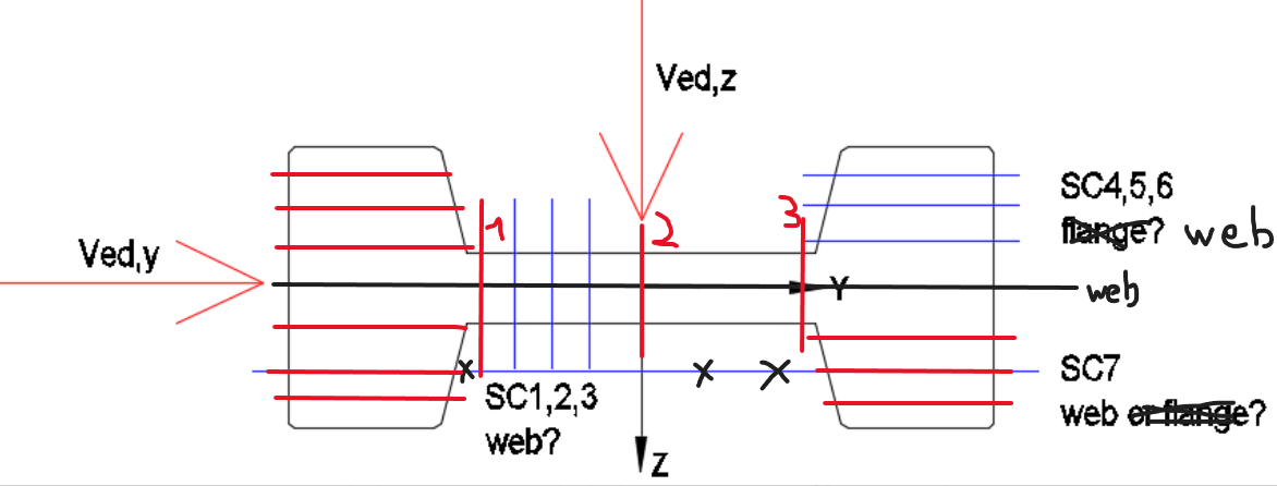
I would initially define all sections here as WEB.
Sections 4, 5 and 6 will take part in resisting both My/Vz and Mz/Vy and all cut the same stirrup legs; therefore they should receive their own layer number. The layer number of a shear section practically corresponds to a stirrup element that is cut by that shear section.
I would arrange shear cuts like numbers 4, 5 and 6 in all four “ears”. All shear cuts in the right “ear” receive a common layer number, and all cuts in the left “ear” receive a common but different layer number.
I would distribute shear sections 1, 2 and 3 across the width between the ears. These also get a common — but again separate — layer number, since these cuts in turn cut the legs of another stirrup.
Further I recommend to study Verificaton Examples DCE-EN6, DCE-EN7 and perhaps DCE-EN10 under SOFiSTiK VERiFiCATiON Benchmarks 2026 for a better understanding.