I have a bridge structure where a deck is comprised of bridge deck with one or two beams and it is also in a curvature (situation). Beam of a bridge deck has a variable height along the axis and it also has a slight transverse slope.
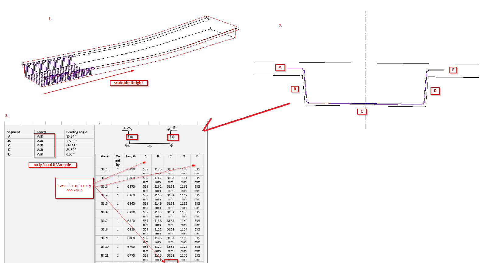
My goal is to have transversal rebar set geometry to follow the beam along the axis and have the variable height (screenshot 1.)
The bridge deck has a variable height along the axis, which means I would like to have variable segment heights of a rebar: B and D. (screenshot 3)
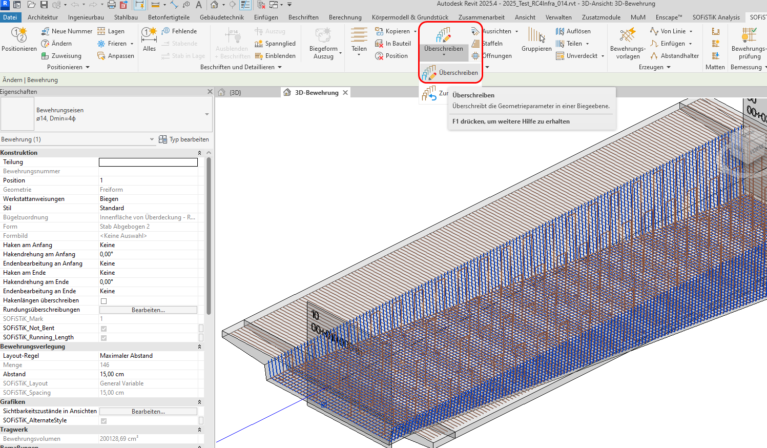
I model the rebar using Free Form tool in Revit and I have to adjust the rebar sets and positions according to stations of the bridge deck (so the variable segments go from highest to lowest value)
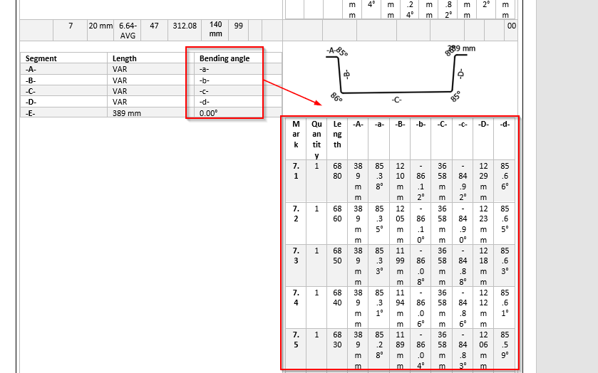
In the schedule the software detects the smallest changes even in milimeters, so what ends up happening is that there is a variability in all segments of the rebar. When I export the schedule, this is not the desired situation. I only want the segments B and D to be variable.
You can see that for example in segment C detects the difference of 1 milimeter from value 3659 mm to value 3658mm.
My question: Is there a setting or a workaround in software to neglect these small changes and have only desired segments variable?