The example here refers to \csm.dat\english\more\csm31_design_aashto_metric.dat
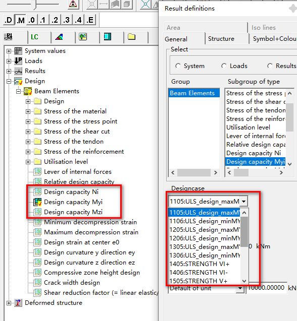
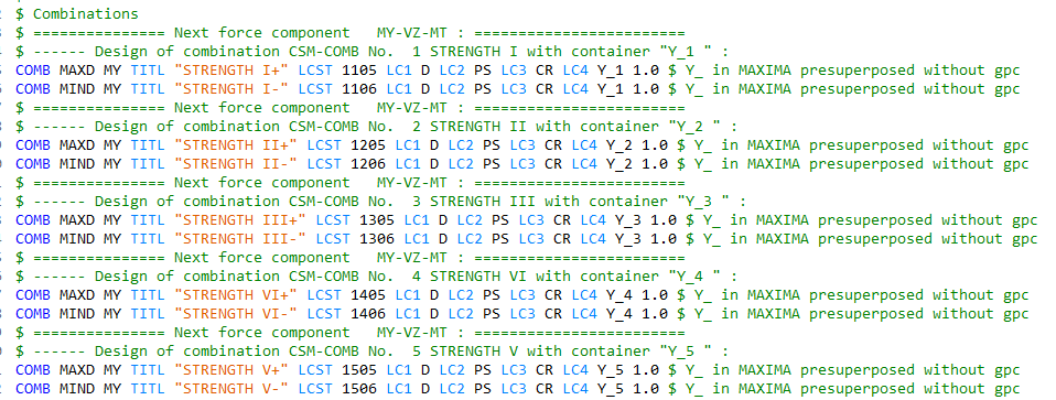
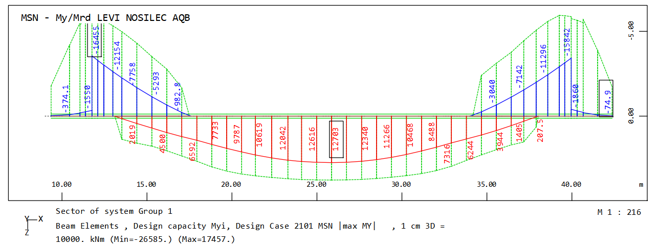
- The term “Design Capacity XXX” in the Graphic is misleading. They looks like “Section Capacity”, but the correcponding teddy code (csm31_design_aashto_metric_maxi.dat) shows that they are internal forces My under different load combinations, they are not “Section Capacity”.
- The above csm31_design_aashto_metric_maxi.dat is created automatiacally by applying
+apply "$(NAME)_maxi.dat"
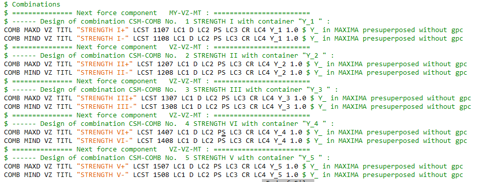
in the csm31_design_aashto_metric.dat. But the shear forces are not calculated in csm31_design_aashto_metric_maxi.dat. Do I have to manually add shear forces, VZ in the case, in the csm31_design_aashto_metric_maxi.dat? Like this
-
Where can I find “Section Capacpty” in the result (report, graphic)?
-
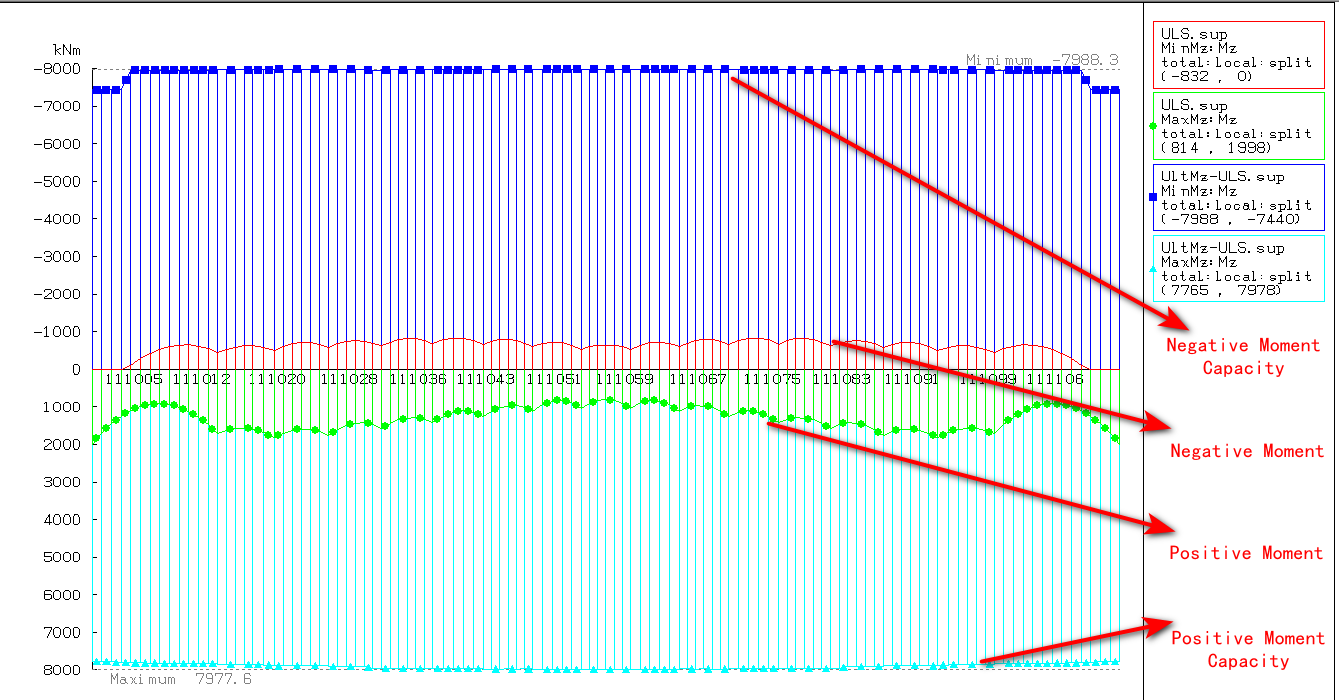
Can Sofistik show diagrams of both internal forces and the corresponding section capacities along structural member? Like this one from RM Bridge (TDV). How to achieve this?
-
The moving load will creat load envelop, eg. MaxN, MinN, MaxMy, MinMy. When checking longitudinal stress or calculating section capacity My, Does Sofistik use MaxN (MinN) or concurrent N?
1 Like
Hello
add 1.
Design Capacity or Section Capacity I don’t know what is correct, but it is maximum ULS desing bending moment (taking into account the reinf. As and N force). In eurocode so-called “Mrd”, similar like here
add 4.
It is possible but it’s complicated. You have to do some acrobatics in wingraf … additional layers in graphic.
eg:
1.layer: Desing capacity Myi : LC max
2.layer: Bending moment My : LC max
similar for LC min …and when showing LC max supress negative zone and vice versa …and additional corection of colours…then you can get:
Thank you
Q1: Yes, I mean “Mrd” for moment capacity. How do you get this in Sofistik?
BTW: I think Eurocode also need to check shear, torsion capacity, how do you get them in Sofistik?
Q4: As for “and when showing LC max supress negative zone and vice versa …and additional corection of colours…then you can get:”. Is it possible to show me an example (teddy is perferred) file?
Q1:
It’s dificult to explain but in general, the design capacity you get if you run ULS desing in module AQB.
in teddy: DESI ULTI in module AQB…
Q4:
my case in module WING
MOVE DEL; MOVE 2 92 UNIT PR ALIG LEFT
TEXT "ULS- My/Mrd MAIN GIRDER AQB"
COLO C13 3005 -1; LC DESI 2101; BEAM DCMY SCHH NO UNIT 10000; AND
COLO C13 -1 3005; LC DESI 2102; BEAM DCMY SCHH NO UNIT 10000; AND
COLO C13 2001 -1; LC 2101; BEAM MY UNIT 10000; AND
COLO C13 -1 4001; LC 2102; BEAM MY UNIT 10000
LC max is 2101 and LC min is 2102
1 Like
COLO C13 2001 -1; LC 2101; BEAM MY UNIT 10000
Which part in the above code supresses negative zone?
I think -1 it’s the short version of colour input, the regular input shoud be:
COLO C13 2001 C14 -1
C13 positive results, value 2001 (red) C14 negative results, value -1 (no colour)
see also PDF help for graphic (F1 in teddy)
1 Like