https://docs.sofistik.com/2026/en/rhino_interface/grasshopper/components/TendonGeometryProfile.html
Is it possible use illustration to show what are the meanings of “Pts A, Pts B, M Type, Align H” and relations between these terms and PT profile?
https://docs.sofistik.com/2026/en/rhino_interface/grasshopper/components/TendonGeometryProfile.html
Is it possible use illustration to show what are the meanings of “Pts A, Pts B, M Type, Align H” and relations between these terms and PT profile?
Hi there!
We actually have a deep-dive article on this very subject in the works. As we are still a few days away from it being online and available, I will copy and paste the relevant content here for you. Hope it help!
Regards,
Wojciech from SOFiSTiK
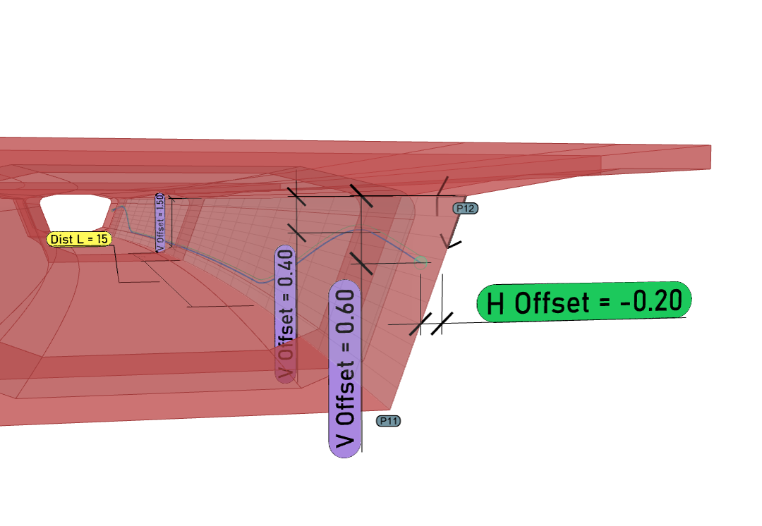
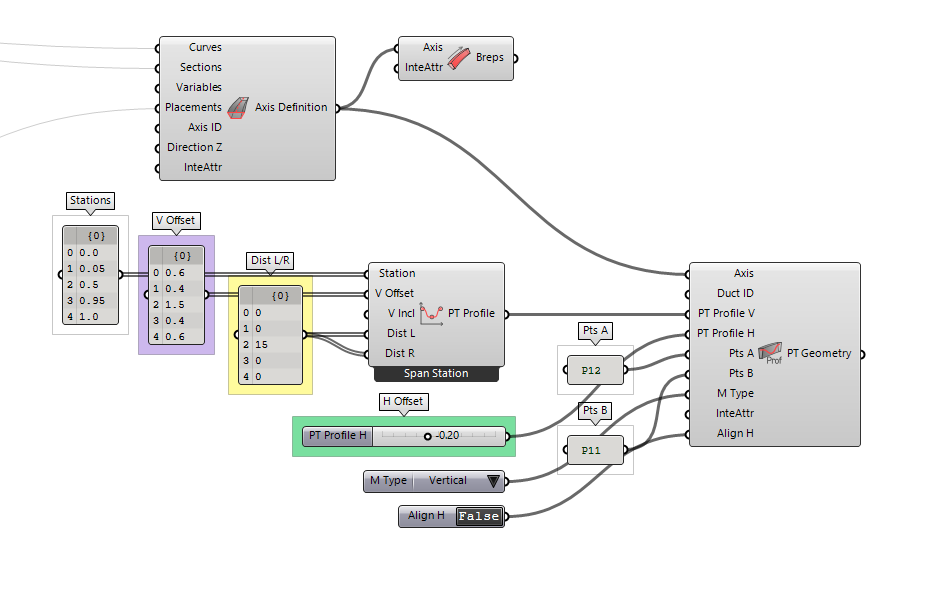
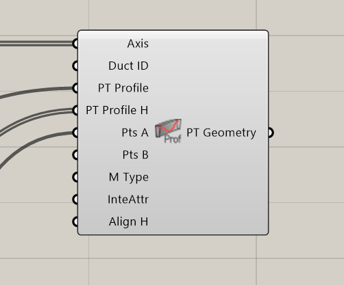
- Builds on the PT Geometry Spline component to transform 2D profiles into fully parametric 3D tendon duct geometry, projected onto a spatial plane defined along the Axis. The concept relies on combining a vertical planar profile with an optional horizontal profile to shape the final 3D tendon path.
- The PT Profile V defines the vertical planar shape of the tendon, either as a fixed offset or a dynamic input from the Profile | Spline or the Profile | Polygon components. This profile is projected onto a spatial plane along the Axis to generate the 3D tendon path.
- The PT Profile H input adds the horizontal tendon profile, either as a numeric transverse offset or a second 2D profile, allowing full control of tendon geometry across the depth or width of the section.
- If Point A is specified, it defines the origin of the projection plane. Otherwise, the Axis reference point is used.
- If Point B is provided, the plane is aligned along the A–B direction. If not, global Z is used as the vertical direction
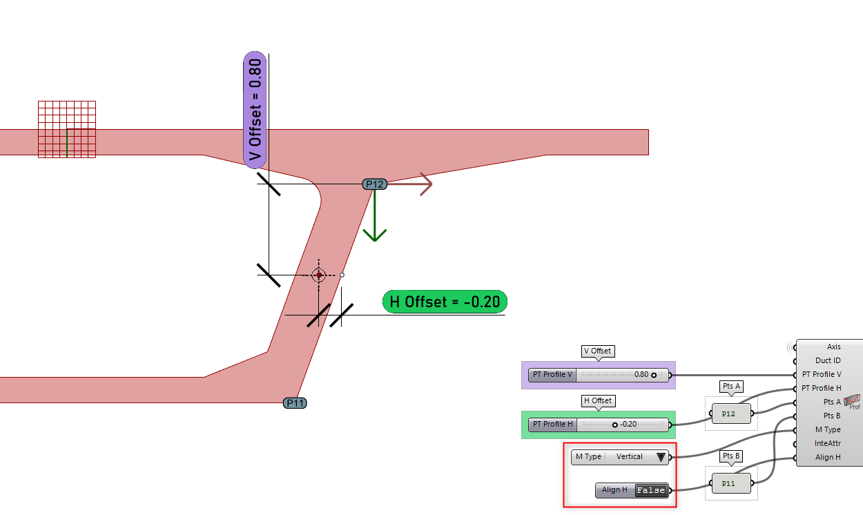
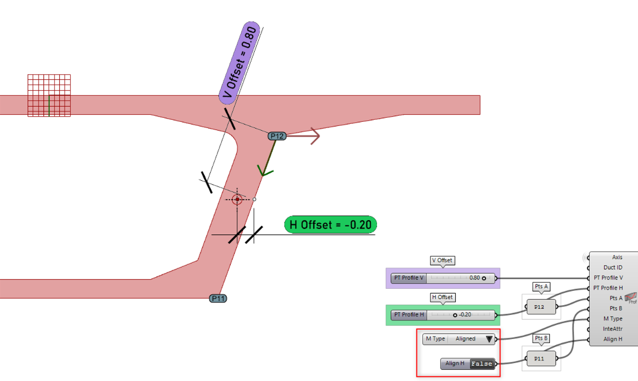
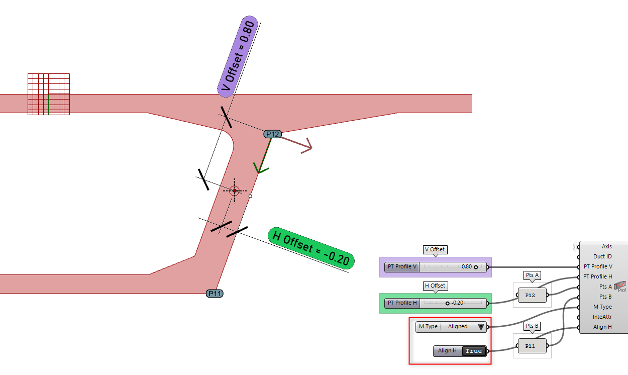
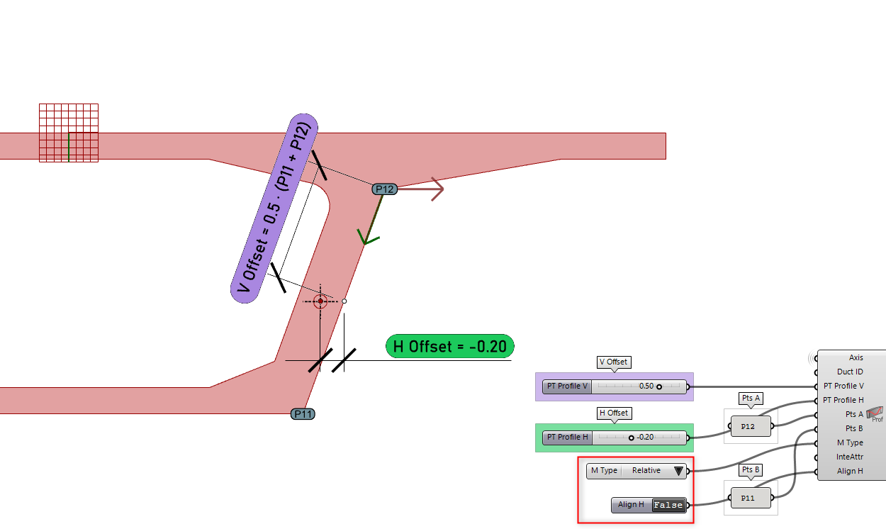
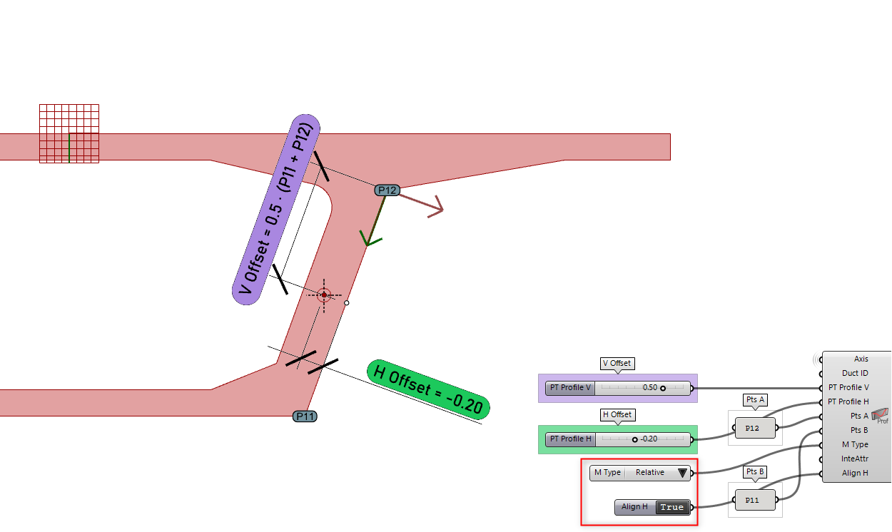
The positioning of tendon profiles projected with PT Geometry Profile depends on two key parameters: Measurement Type M Type and the Align H boolean.
M Type controls how the input profile is interpreted in the workspace:
- Vertical: vertical offsets are measured globally along the Z-axis.
- Aligned: offsets are measured along a vector defined between Point A and Point B.
- Relative: offsets represent a percentage of the distance between Point A and Point B.
- FromOrigin: offsets are measured relative to the Axis origin. FromOrigin can be separated from other MType by a comma ‘,’.
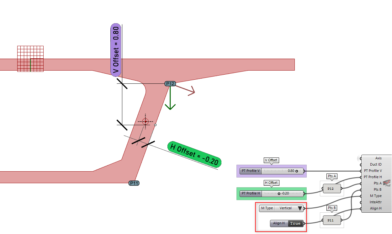
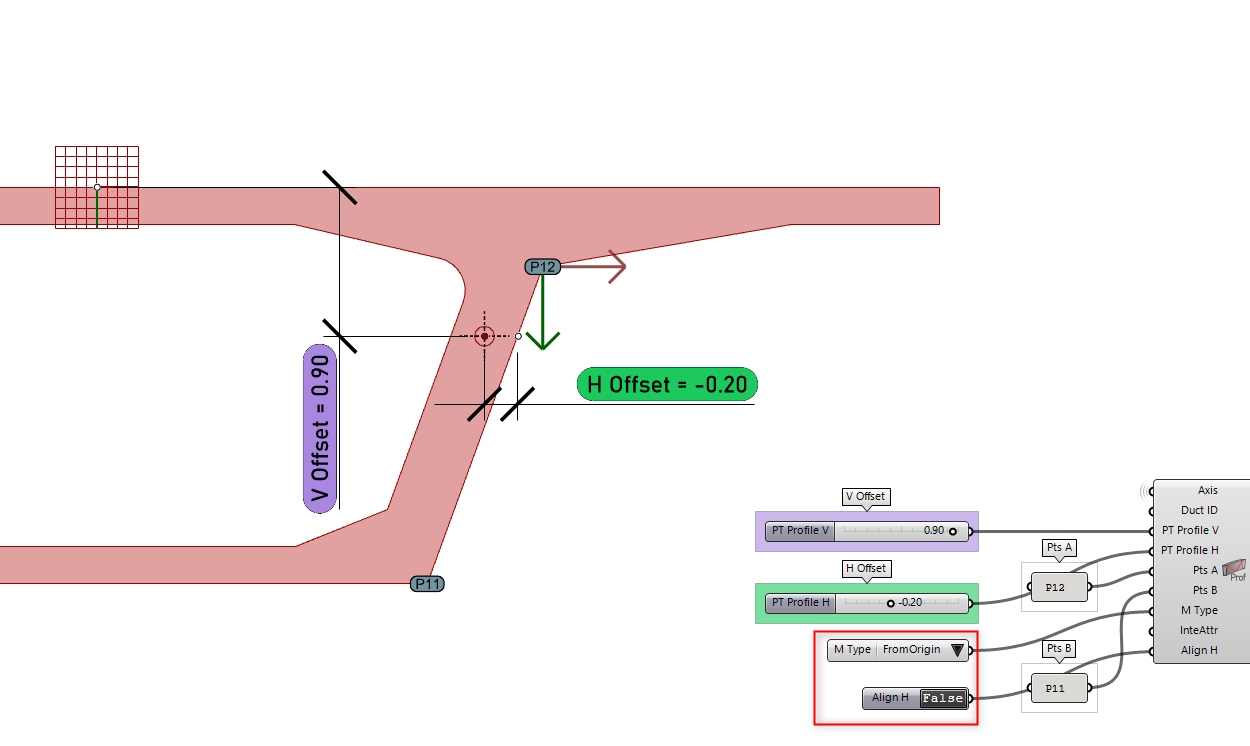
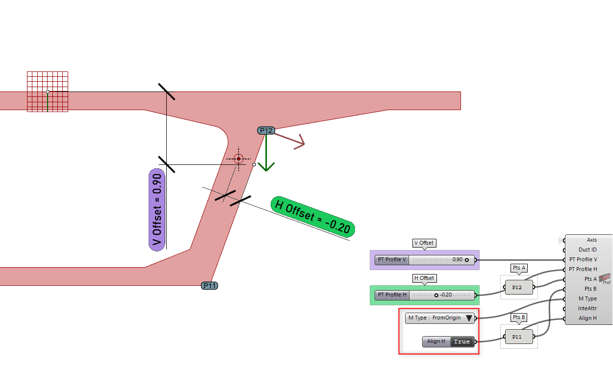
The Align H setting determines how the H Offset is oriented:
- False: horizontal values follow a fixed horizontal direction.
- True: horizontal values are measured perpendicular to the A–B vector.
The following examples illustrate how various measurement types and alignment options influence the final placement of fixed V/H offsets within a cross-section.