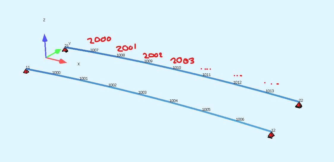
I have a simple model of two parallel beams. I have defined 4 points (SPT) that are their support nodes, and using SLN with negative SDIV values defined number of elements for each beam. I would like to have one beam with the node numbers 1xxx and the other 2xxx, but they are both in the range 1xxx. How can I offset the numbering so I achieve it, preferably without manually generating all nodes with a loop?
it is possible, but only for user defined nodes. Its easy to achive with axis, secondary axis and definning placements like:
GAXP ‘A1’ ids ‘A’ S #X spt 1001+#i
GAXP ‘A1’ ids ‘B’ S #X spt 2001+#i
However for autogenerated nodes they are going to have first free number above defined with CTRL NODE
The beams are actually arching, which made me choose the GAXB record, and GAXS with SPT parameter but it had no effect. May be because the nodes are auto generated, and thus this parameter is ignored as you said.
Im confused as to how many records are necessary after defining the GAX. For my case here, is it recommended to have GAX, GAXB, GAXS, and GAXP?
I like using SLN because then I able to set start and end points from already defined notes, and easily able to choose the number of elements that are then of equal length.
Using the axis approach, because I cannot simply choose start and end nodes (as I read it in the documentation). Then dividing the axis into elements by stationing, because of the arc, the elements will not be of equal length.
In my system, there are exactly 20m between supports, but the true length of the arc will be longer. Complexity greatly increases now, as I have to calculate the increment that will make the end node exactly meet the support node.
It should not be like this, with axis you can define plan and veritical geometry separatly so span lenght should be correct. Can you provide a teddy code so we can review it?
My understanding is that the stationing S variable follows the curve of the axis, and is not the overhead view (ie the horizontal projection). I want every segment to have the same true size.
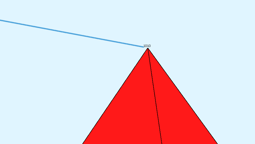
How should I make the beams end at the appropriate support nodes with no gaps?
+prog AQUA urs:1
head Design Codes, Materials, and Cross Sections
!*!Label Design Codes
norm DC DS EN199X-200X-BRIDGE
STEE NO 1 type S CLAS 355
!*!Label Steel Profiles
prof no 1 type RHS z1 200 300 10 // bottom chord
prof no 2 type RHS z1 200 8 // top chord
prof no 3 type RHS z1 120 5 // diagonal members
prof no 4 type HEA z1 300 // cross beams
prof no 5 type L z1 150 90 9 // stiffeners of steel deck plate
end
+prog sofimshc urs:2
head Geometric modelling
syst type 3d GDIV 10000 GDIR NEGZ
CTRL OPT MESH 3
CTRL OPT HMIN 1.0
STO#L 20.0 // LENGTH OF BRIDGE FROM POINT TO POINT
STO#H 2.9 // HEIGHT AT MIDPOINT
STO#NSEG 8 // NO OF SEGMENTS LONGITUDINAL
STO#W 5 // WIDTH OF DECK
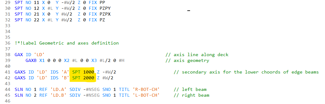
SPT NO 11 X 0 Y -#W/2 Z 0 FIX PP
SPT NO 12 X #L Y -#W/2 Z 0 FIX PZPY
SPT NO 21 X 0 Y #W/2 Z 0 FIX PZPX
SPT NO 22 X #L Y #W/2 Z 0 FIX PZ
!*!Label Geometric and axes definition
GAX ID 'LD' // axis line along deck
GAXB X1 0 0 0 X2 #L 0 0 X3 #L/2 0 #H // axis geometry
GAXS ID 'LD' IDS 'A' Z -#W/2 // secondary axis for the lower choords of edge beams
GAXS ID 'LD' IDS 'B' Z #W/2
GAXP ID 'LD' IDS 'A' S 0 SPT 1000 NCS 1
GAXP ID 'LD' IDS 'B' S 0 SPT 2000 NCS 1
LET#INCR #L/#NSEG
LET#SX #INCR
PRT#INCR
loop#i #NSEG
PRT#I
PRT#SX
GAXP 'LD' IDS 'A' S #SX spt 1001+#I
GAXP 'LD' IDS 'B' S #SX spt 2001+#I
let#SX #SX+#INCR
endloop
LOOP#I #NSEG+1
SLN NPA 1000+#I 2000+#I SNO 4
ENDLOOP
$SLN NO 1 REF 'LD.A' SDIV -#NSEG SNO 1 TITL 'R-BOT-CH' // left beam
$SLN NO 2 REF 'LD.B' SDIV -#NSEG SNO 1 TITL 'L-BOT-CH' // right beam
$SLN NPA 11 NPE 12 SNO 1 SDIV -#NSEG
$SLNB X3 #L/2 -#W/2 #H
$SLN NPA 21 NPE 22 SNO 1 SDIV -#NSEG
$SLNB X3 #L/2 #W/2 #H
$LOOP
$ENDLOOP
end
!*!Label Geometric and axes definition

GAX ID 'LD'                                            // axis line along deck
    $GAXB X1 0 0 0 X2 #L 0 0 X3 #L/2 0 #H               // axis geometry
    GAXA X 0 y 0 z 0 S 0 L #L sx 1 sy 0
    GAXH S 0    H 0
    GAXH S #L/2 H 6.333 R 18.691379
    GAXH S #L   H 0


GAXS ID 'LD' IDS 'A' y   -#W/2                     // secondary axis for the lower choords of edge beams
GAXS ID 'LD' IDS 'B' y #W/2

GAXP ID 'LD' IDS 'A' S 0 SPT 1000 NCS 1
GAXP ID 'LD' IDS 'B' S 0 SPT 2000 NCS 1

LET#INCR #L/#NSEG
LET#SX #INCR
PRT#INCR
loop#i #NSEG
PRT#I
PRT#SX
GAXP 'LD' IDS 'A' S #SX spt 1001+#I
GAXP 'LD' IDS 'B' S #SX spt 2001+#I

let#SX #SX+#INCR
endloop

LOOP#I #NSEG+1
SLN NPA 1000+#I 2000+#I SNO 4
ENDLOOP
You control tangent intersection point, which is connected with high point of an arc by geometric realtion, so you need only introduce some mathematics which will yield from #H and #L to tangent IP and radius which I did in CAD.
It is a way to define plan and vertical alignment separatly, you could achive the same your previous method with some modification like multiplication of length by ratio of arc to straigt legnth,
however it is up to you since you are an engineer