I am modeling a beam with beam element and same beam with shell elements, In order to compare the difference in result between them. I need to compare stress at a particular plane. for beam element I can obtain easily but for shell elements I got stresses for each quad element. Is there any way that I could obtain same type of figure for shell element at certain plane rather than stresses at each particular node so that comparison could be possible. Is there any other way to do that is sofistik .
You can visualise the results with the Graphic or the Resullt Viewer.
With the Graphic you can filter the results for a specific plane with the comands “Box” or “Group” (if you defined different groups) .
For a thorough introduction to the Graphic, see our online bridge design tutorial.
The Result Viewer is used to create tables, graphics and diagrams.
Best regards
Frederik Höller
Your SOFiSTiK Support Team
Thank you for your reply ,
I tried to get stresses using cuts, and also using sir cut but I wasn’t able to get exactly at the plane I wanted. This might be the problem due to lack of my knowledge of sofistik. couldn’t find right example to proceed further.
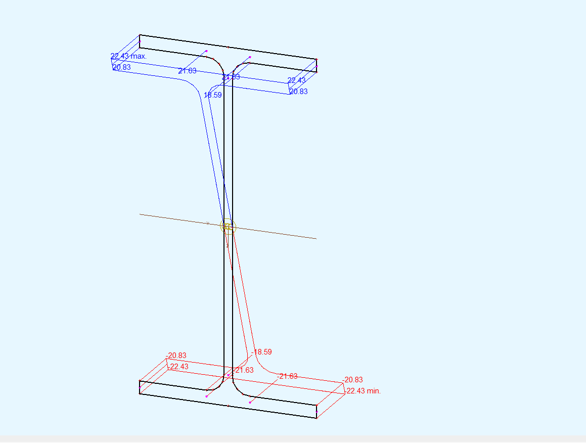
Can you help me to create a cut either with wingraf of teddy with instruction ( if possible, much appreciated) to creat a plane at center of beam where deflection is maximum in order to check the stresses in local x direction at beam cross-section attached in the attachment.
Ok at first I would select a regular meshing for the structural areas.
In order to get the stresses exactly in the middle of the beam, you need the element edges to be vertical. So I would create a “dummy” beam (SLN) with no cross section at the position to be examined. (Another option is to divide the structural areas in the middle into two SARs)
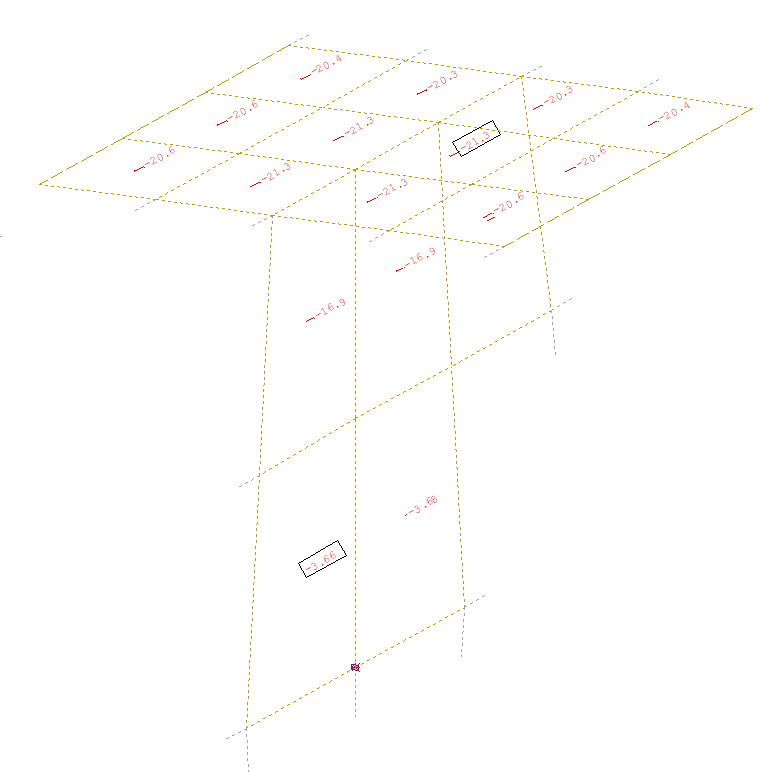
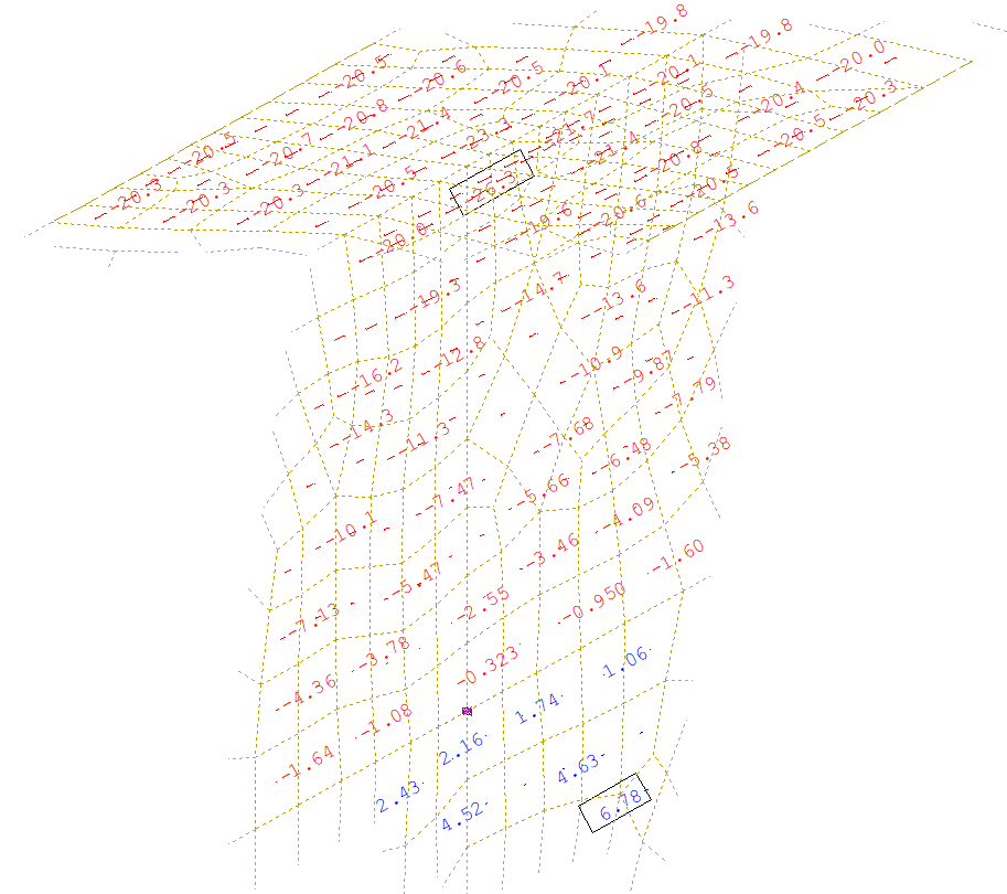
In the programm Graphic you can now only select the FE-Elements in the middle of the beam with the “BOX” command. In a next step you can investigate the element-stresses. You have to keep in mind, that these QUAD-stresses are in the middle, at the top or at the bottom of the QUAD-Element.
Also, you need to consider the element size. The smaller the edge length of the QUAD elements, the finer the result.
")