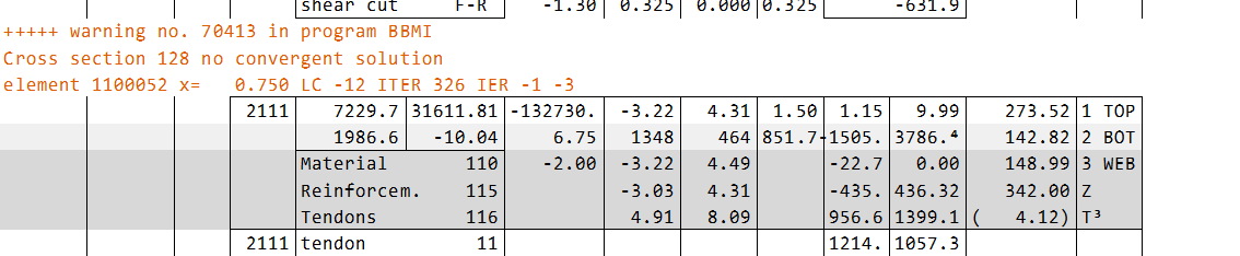
I have a question regarding my model. When I run the calculation for CSM Bridge Design (Beams), after the ULS calculation I receive a warning message indicating that, for some beam elements, there is no convergent solution for certain load cases.
Additionally, I would like to mention that I have disabled the automatic increase of longitudinal reinforcement in beam elements by using the command CTRL REIN FIXL.
My questions are as follows:
What does IER -1 -3 mean?
What does “no convergent solution” imply, and how does it affect my results?
I ask because, in the report, it appears that the cross-section still has sufficient bearing capacity, and it is not clear to me what exactly is failing or not converging.
In principle, the goal of AQB is always to find an equilibrium during the iteration process. One criterion for this is that value “rel” (the relative load capacity), multiplied by the acting internal forces, matches the capacity (of internal forces) of the cross section in the ultimate limit state.
You can find more detailed information on this topic here:
in video “#12 – Design with CSM” in chapter “03 Output of check print – ULS design”, specifically from minute 28:43 to 31:02.
Due to various reasons, numerical issues may arise during this process. Then this criteria is not fullfilled and warnung 70413 can appear.
By the way: The maximum value that can be reported for ‘rel’ is 9.99. In such a case, you need to backtrack and check whether ‘rel’ is the same for all three internal forces (N, My, and Mz). If this is not the case there is the same problem and warning 70413 can appear.
There are several ways to still achieve a valid design. Below, you’ll find a standard text we typically provide:
The reason is that the algorithm is not perfect. Under consideration of a strain variation AQB tries to calcu-late the necessary reinforcement. Depending of the number of reinforcement layers and the number of other boundary conditions it’s possible that there isn’t a well-defined solution.
In such cases the user must decide what to do. He should check some things (point 1 - 3) and use the pos-sibilities (point 4-10) - perhaps by try and error - to solve the problem.
Basically you shall minimize the number of layers.
You should define for torsion an own layer as supplementary (Z-layer), torsional action active (RF … TORS ACTI)
All other layers are minimum reinforcement layers (M-layer), torsional action passiv (RF … TORS PASS)
If you have a “problem-beam” only view this explicit beam with internal forces. Perhaps you define a special AQB-run with this one special combination of internal forces (N, Vy, Vz, My …).
You should check the stresses of the concerned beam in Resultviewer and the internal forces in Reportbrowser (define ECHO FULL EXTR in the aqb-run); then perhaps you realize some problems.
You should define a minimum and maximum of reinforcement for all layers to reduce the possibilities in the iterative processes.
You can change the weighting factors, for example with „REIN P7 10" or „REIN P10“ (see manual).
7.1 An increase in the number of iterations (CTRL IMAX) and/or the tolerance (CTRL ETOL), and/or a reduction of the parameters CTRL AMAX and AGEN can help.
7.2 Fixing the reinforcement using CTRL REIN FIX can also help.
You can adjust parameters DESI … C1, C2, S1, S2.
Sometimes there is the problem that the moment is almost „0“. Then there isn’t a well-defined solution. The option “REIN P7 10” could help then. Or the definition of a minimum reinforcement with “DESI AM1… AM2… AM3… AM4…”. Therefore you can try these possibilities.
If there are some beams left with warnings you must define a design only for these beams with different adjustments.