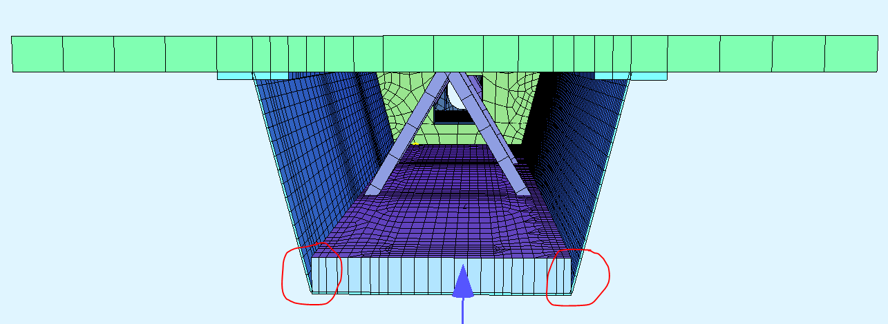
I am working on a double composite steel-concrete box girder bridge model. I am currently refining the model and an issue I have come across is that the bottom concrete slab is not connected to the bottom of the web of the box girder due to the way I have modelled the different elements in grasshopper as seen in the figure below.
Would anyone have any advice on how to model this connection of the concrete and steel? I am looking to study the impact the bottom slab has on the web and its buckling behaviour.
As I don’t know how you modelled the system, I can only give you some hints.
Have you tried to model the two structural areas (concrete and steal) in the same layer?
In this way, both areas must have the same FE nodes, otherwise they are not connected.
A simple solution for this problem is to couple the two areas with SOFiMSHA. In this workflow, the two areas can even be a few centimeters apart.
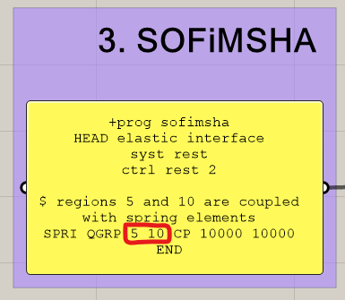
So add a new panel with the following code after the SOFiMSHC block:
+prog sofimsha
head elastic interface
syst rest
ctrl rest 2

$ regions 5 and 10 are coupled with spring elements
spri qgrp 5 10 cp 10000 10000
end
To visualize the workflow, I created a short example. SAR gleiche Lage.gh (20.7 KB)
Best regards
Frederik Höller
Your SOFiSTiK Support Team
I will give that a try. The different elements share the same nodes but the structural areas are defined above and below the lines. This means that when the areas are meshed the concrete slab which is on top goes vertically but has no interaction with the diagonal steel web members.
Since I cannot upload files since I am a new forum member I
have attached an image of the way that the bottom slab (concrete) and bottom flange (steel) have been modelled
I have given it a try. However this error comes up:
“error no. 2029 in program SM_IA_SPRI ; input line: 9 Element number 1 has no length resp. direction”
I also do not think it is what I am trying to do, this seems to be coupling two areas that are parallel to each other, in my situation the areas are perpendicular and it is only a portion of one area that i am trying to couple or create and interface to the other.
Ok then I misunderstood your problem.
Can you please upload your project files so I can take a look? I think this is the quickest way to solve your problem;) . (I updated your forum status, now you should be able to upload files.)
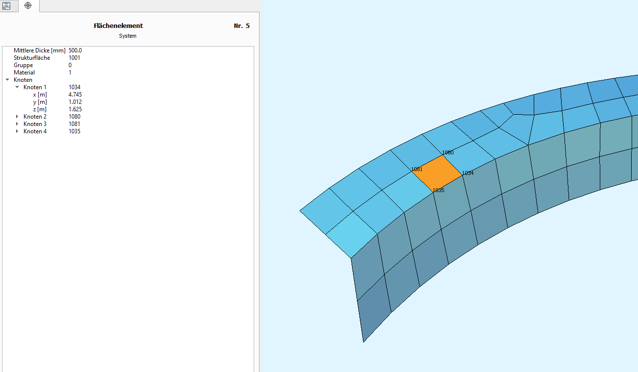
Try to check if the QUAD elements share the same node numbers (see screenshot).
The allignment of the strucutral area should not effect the connection of two SARs, if they share the same nodes in SOFiSTiK.
If not, try to reduce the system to the two connected structural areas and check the relevant QUADs again.
Try to find the command that is causing the incorrect meshing.
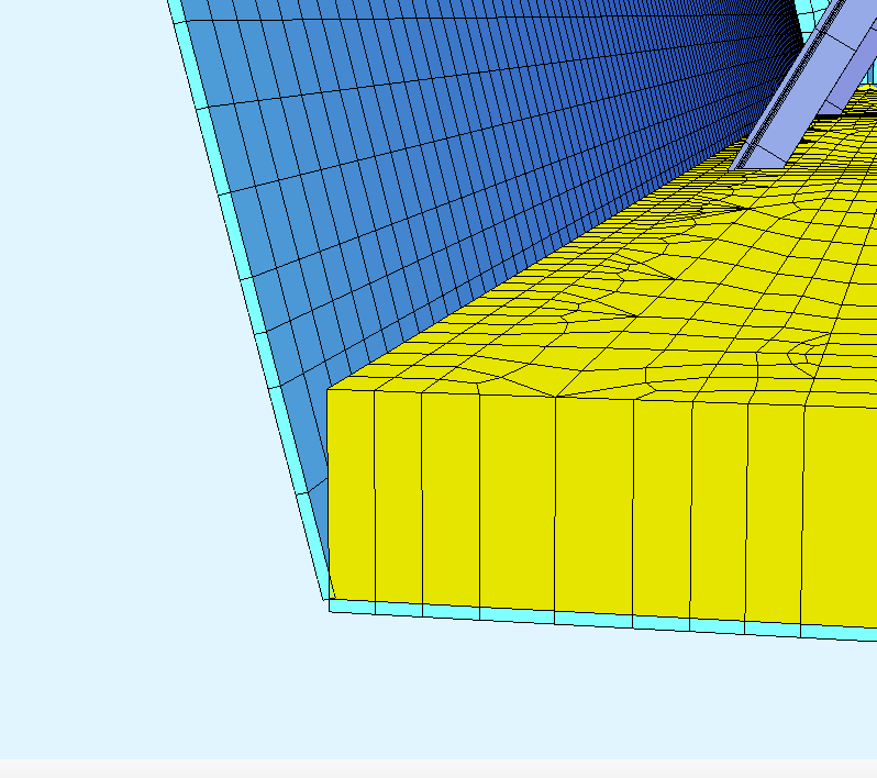
At the bottom where the steel meets the concrete they have the same nodes. However, the top of the slab is not connected to the corresponding location on the steel web as shown in the attached image.
You’ve modelled the bottom flange and concrete as shell elements, i.e. a surface
That means that the concrete only adds to the stiffness (bending and axial) of the bottom flange.
You can’t “connect” the concrete shells to the web, they already are connected in the corner nodes.
Turn off the thickness visualization in the animator and you’ll see the actual model (fe elements) you have created.
What would be the best way to model the interface between materials? Would it be best to model with solid elements? If so what is the best way to do this? Can it be done with grasshopper or are there tutorials?