Depending on the sub-type at SAR, SOFiMSHC creates and sets
of interface edges to one or both sides of the line and disconnects connected structural regions
accordingly.
+SAR: a single interface edge is created in positive z-direction
-SAR: a single interface edge is created in negative z-direction
*SAR: two interface edges are created in both directions.
What’s the actual application of these three different options? Any simple example?
I want to create line springs between 4 egdes of the slab and 4 beams that below the edges, can I use {±*SAR} to achieve this?
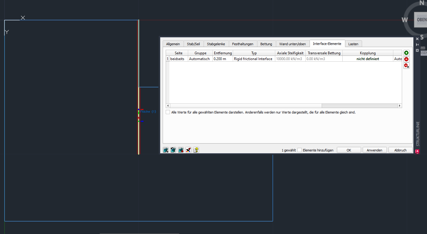
The main use case of interface elements is in soil structure interaction. Imagine a retaining wall. You modell soil with a structure area and the wall with a structure line in a 2d project. To describe the connection between soil and wall, we use the interface elements. My recommendation is to make a small example in SOFiPLUS with interface properties on structure lines and mesh the system
In your case, if you want to connect slab with beams, the interface element cannot be used. You need to model the beams with a distance below the slab and use springs between two structure lines or constraints. Again go into SOFiPLUS and make a litte example to understand the possibilities. That’s a very simple approach to start graphically and go on text based in TEDDY.
Best regards
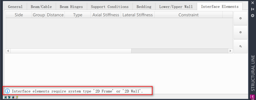
But this infomation is not available in the SofimshC manual.
Is it possible to add an option to define linear spring between edge/internal constraint line of the area and beam?
So I don’t have to divide the area and beam to insert the point spring.
The “FIX” option in SARB is very similar to what I want, but it only allow linear bedding instead of linear spring.
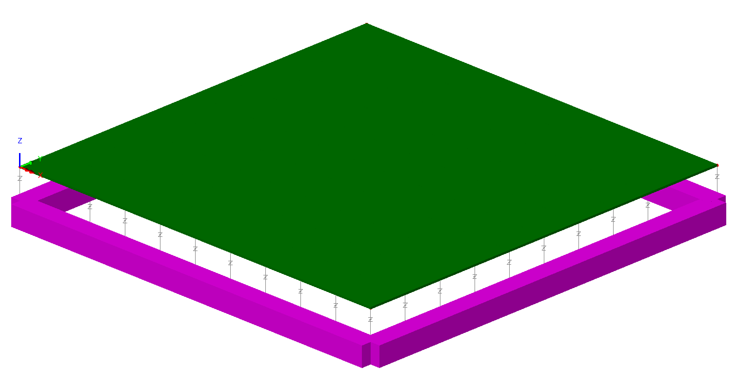
BTW: Lusas has very useful feature to define linear spring between edge/internal constraint line of the area and beam as shown below: the grey lines with “Z” represent linear spring.