Hi, could anybody help to explain how should i define the reference point of a user defined profile in cross section editor. i know there is a selection in standard cross section defination dialogue window. but how do we define in user defined rofile.
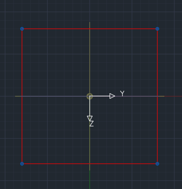
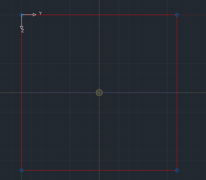
In the cross section editor, the origin of the coordinate system is taken as the reference point. Here are two images with a centric and an eccentric cross section in the cross section editor.
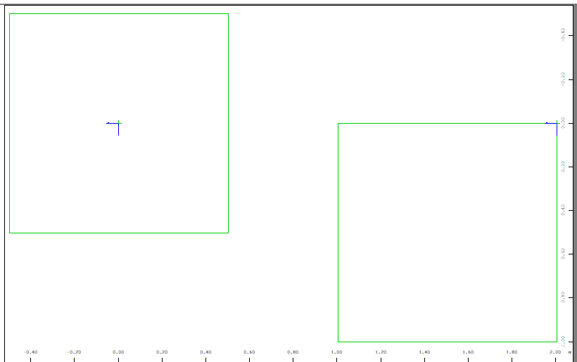
If you assign these cross-sections to structural lines and mesh them, you get this picture:
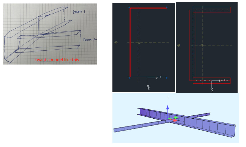
Hi Birgit, i follow your comments do the steps below, but the 2 C profile are not connected by flange surface.
1 what i want to model like the figure below(flanges of C profile touched, load should be able to transfer between these 2 C profile)
2 I follow your commenst to draw the cross section and system as below:
3 The 3D model is like below(C profile crossing, not flange connected each other)
Hi,
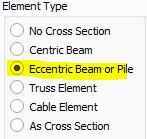
have you selected the ‘eccentric beam’ option in the structural line dialog?
Hi Birgit. yes, i just forgot to select ‘eccentric beam’, now it got fine. BTW, if i have another surface panel on top of Beam 1 with some gap(for example 50mm) between them. then i have to define a point at surface and a point at beam 1 then use point constrain to link them, right?
Hi,
I assume the other “surface panel” is defined with a structural area? Then you have to create a spring or coupling between structural lines.
So you have to define an additional structural line on the structural area (the other structural line already exists) and connect them.
Birgit
Hi, Birgit. Appreciate your help. i have two questions below:
1: Define an additional structure line, i should define this structural line as element type ‘No cross section’, right? because that will not add additional stifness to the surface area
2: Regarding the spring or coupling, i assume you mean ‘line link’ or ‘line constraint’, right? But when i click ‘line constraint’, and then select two structral lines, nothing happend. what is the reason?
Hi,
1: Yes
2: Yes, ‘line link’ or ‘line constraint’. Please always note the text in the command line of AutoCAD / SOFiPLUS-X. You first select all source structural lines, then you finish your selection with return and then you choose the target line.
Hi Birgit:
Yes, it solved. Thanks a lot for all your help in steps.