Bei einer Berechnung im Stahlbau bestehen die Pfosten/Stützen aus aufgedoppelten Flachstählen, d.h. zwei längliche Bleche (100x10mm) im Abstand von 1-2cm die aber nicht schubsteif miteinander verbunden sind.
Ich suche nach einer einfachen Möglichkeit, das im Modell abzubilden, ich würde die Profile danach auch in AQB (bspw. auf BDK) untersuchen wollen. Zwei Ideen hatte ich bisher dafür, bei beiden scheitere ich an Umsetzung:
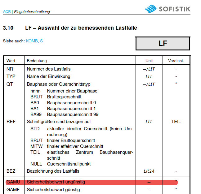
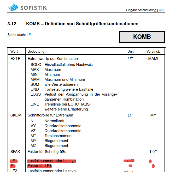
Ich gebe in AQUA den einfachen Querschnitt ein. Die erhöhte Steifigkeit erzeuge ich über GRUP FAKS 2.0. Danach bräuchte ich aber für die Bemessung immer die halben Schnittgrößen (ich habe gute Gründe davon auszugehen, dass sich die Lasten recht gleichmäßig auf beide Profile aufteilen). Leider gibt es keine Möglichkeit, in AQB dafür einfach einen Faktor einzugeben bei LF bspw. Kann man die Schnittgrößen aus den nicht linearen Lastfällen einfach in einen neuen Lastfall “kopieren” und mit einem Faktor 2.0 versehen?
Alternativ müsste ich einen Querschnitt “Doppelstütze” erzeugen, der aber berücksichtigt, dass die Querschnittsteile nicht schubsteif verbunden sind und dies auch in der AQB Bemessung noch versteht. (also bspw. Querschnittswerte mit QUER modifizieren hat bei mir nicht funktioniert, weil die Querschnitte dann in AQB nicht mehr zu gebrauchen sind). Geht das irgendwie?
I have tried this, and this creates all kinds of problems i’d rather avoid, clamping of the beams, constraints, tricky connections with couplings or springs, etc.
In my opinion this only unnecessarily increases only the complexity of the model. I believe based on the real geometry that it’s reasonable to assume that the load gets distributed evenly on both columns.
All I want to do is multiply the sectional forces (or the cross section values) by a constant factor before dimensioning, i can’t believe that this is not possible.
You cannot change the combination coefficients in aqb (there is no gamu keyword). That would also have been my preferred option.
I tried the latter but the results are wrong too, as there are loadcases with internal constraints due to temperature, movement etc. Also they are non-linear so running them with half the load won’t produce half the internal effort later on.