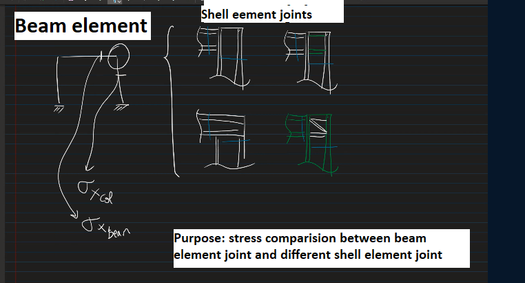
I want to compare the stress at steel joints. The stress at the joint needs to be compared between the frame created using beam element( (using steel I-section) vs frame created using shell element (using steel I-section) . The problem is I couldn’t assign steel stander I-section to model frame using the shell element. Can you please recommend a video/text where and how I can model the I-section steel frame using a shell element. Is it possible through SOFiplus or teddy ?
Hello
So you want to model the Beam with Shell elements. That’s pretty easy. All you have to do is draw and extrude the cross-section elements (flange, web) in sofiplus. Now you can assign structural areas to the areas.
I have attached a short example for an I-Beam (I 200). You just have to think about a suitable support condition.
Steel beam shell.sofistik (24.4 KB)
Steel beam shell.dwg (48.7 KB)
Best regards
Frederik Höller
Your SOFiSTiK Support Team
1 Like