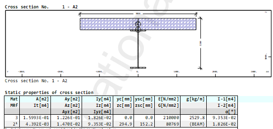
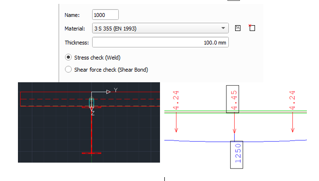
I’m modeling a simply one span composite beam to learn how program works beacause it’s my first steps with Sofistik. Following the tutorial, I created the cross-section shown on the picture
Load of model is a line load of value 10 kN and beam have 10 m length. So i supposed that the correct displacement of this beam should equal 5/384*ql^4/EI = 0,34 mm.
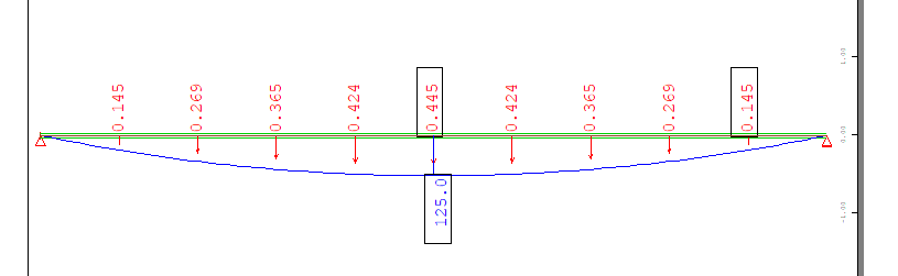
But the result in program is diffrent and maximum displacment equal 0,445 mm.
Thank you for your answer.
In terms of self weight, only a line load is applied to the beam, so the self weight has no effect on the displacement.
I don’t understand how shear deflection work. Can you tell more about them?
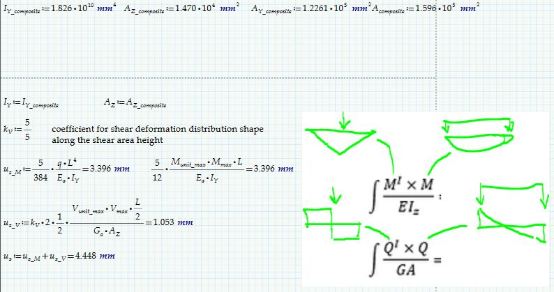
This is formula for general calculation of displacements. As you can see the shear force also contributes to the displacement. This part is ususally very small so we usually ignore it. The difference is too big for it to be responsible. I suggest you first test regular concrete beam, and only then test composite.
Ah ok, Maxwell-Mohre method, thank you
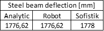
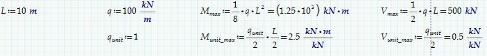
Sure, I started with simple steel beam and checked the results with analityc calculation and diffrent FEM programme (Robot Structrual Analysis). I created one span, 10 m long beam, cross section HEA 100, load = 10 kN/m and comapred the results. In this case I was only considering the deflection of the bending moment (5/384 ql^4/EI).
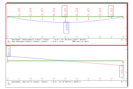
Return to composite beam I added a shear deflection according to your advice and I increased the load to 100 kN/m.
Calculating with bending moment and shear force:
It took me awhile but I found the answer.
SOFiSTiK uses a more advanced beam model, which is the Timoshenka beam, in which the shear parameters of the beams influence the distribution of internal forces and their displacements. Therefore, you cannot directly compare the results from classical mechanics with the results in SOFiSTik. Unfortunately, I do not know in more detail the assumptions and the whole theory of the Timoshenka beam, but the main one is the influence of the shear parameters
I have the another question, maybe you can help me
How to consider the reinforcement in cracked beam?
How to show only one beam from whole bridge in wingraf?
You can determine stresses for cracked section with nonlinear ase run, but first you have to determine reinforcement for a lets say linear load case otherwise there can be no equilibrium when concrete cracks. So first ase linear, then aqb and then:
example:
+PROG ASE urs:5
HEAD
SYST PROB nonl
LC 1
nstr kmod s1 ksv uld ksb uld
END
By isoliting groups. You assign the beams to groups in sofiplus. And then in wingraf:
I did a quick check of the deflection calculation and the conclusion is that Sofistik (u_z=4.45mm) result is pretty close to the analytical one (u_z=4.448mm)
As it was pointed out, Sofistik calculates deflections considering Timoshenko beam theory.
This means that beams with high and thin webs will tend to give a significant shear deformation contribution to the overall deflections.
You did calculate the shear deformation contribution, but you used the horizontal shear area (A_Y) instead of the vertical shear area (A_Z). With the vertical shear area analytical deflection gets very close to the one from Sofistik.
Thank you for example.
Can you send me any material about deflection in Timeshenko beam? I had never hear about vertical and horizontal shear area and coefficient k.
I wrote a little mistake in my calculation. Coefficient k_v is used to transform the total cross-section area A_tot into the effective shear area A_shear, i.e. A_shear=A_tot/k_v.
The area shown in Mohr integral is A_shear. So you do not need to use k_v if you use A_shear directly.
From the text books you will see that k_v=tau_max/tau_average=A_tot/A_shear
tau_max - max shear stress (VS/Ib)
tau_average - average shear stress (V/A_tot)
There are quite a few books describing shear deformation effect on beam stiffness (Timoshenko beam). You can check the following books for explanation:
“Elements of Strength of Materials 4th edition” Timoshenko - §8.5 Deflection Due to Shearing Strain
“Strength of Materials 2nd edition” Timoshenko - §39Effect of Shearing Force on the Deflection of Beams
“Roark’s Formulas for Stress and Strain 7th edition” - §8.10 Beams of Relatively Great Depth
All of the listed books are rather popular and can be found for free on Internet just by googling them