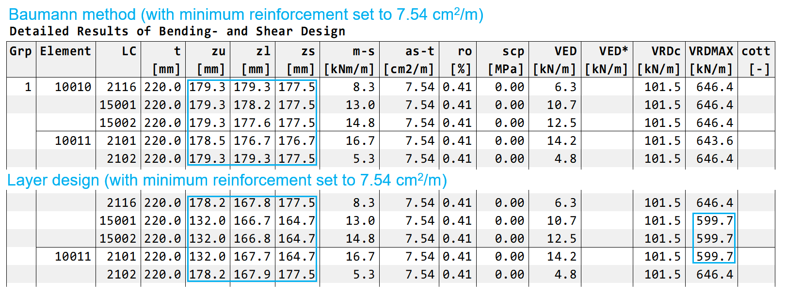
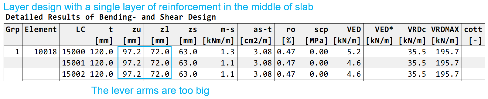
It can be seen that there are significant differences in lever arm values and in certain cases also in VrdMax values. I know that the Baumann method is strongly dependent on the lever arm value. However, the layer design method does not need a certain selection of lever arm. So the first three questions are:
1.1. In the case of Baumann method are the lever arms “zu” and “zl” given in the table the same that are used in the calculations to divide moments into force pairs as described in the BEMESS manual? 1.2. How is the lever arm in shear design “zs” calculated? 1.3 Is there a bug in representing the lever arms in the table for Layer design method?
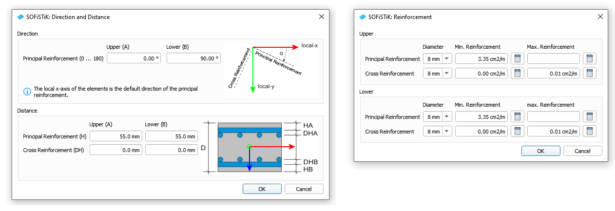
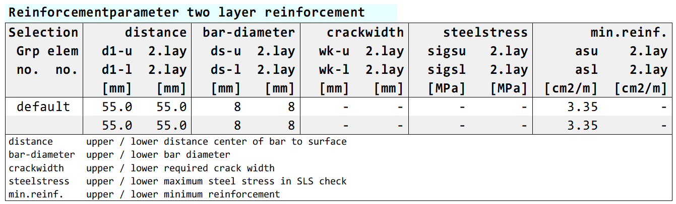
2. Design of a slab with single layer of reinforcement
I have also tried using the layer design method to design slabs with a single layer of reinforcement with the following settings:
The question is as follows: 2.1. Despite the wrong lever arm values represented in the table, are there any other reason why one should avoid designing slabs with a single reinforcement layer with Sofistik?
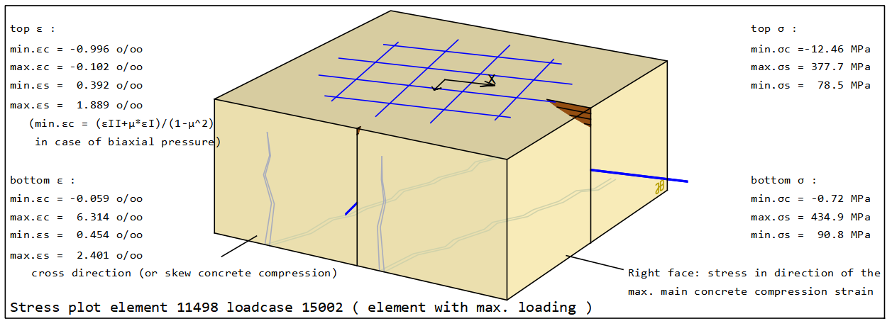
Zl and Zu are only two representative values of a 2D-system in different directions. BEMESS tries to present it best in only two values, assuming that in both direction there exists a reasonable compression area and the minimum lever arm is 0.6*h . That’s not always the case, therefore, the value is written there is not fully traceable. These assumptions may change in the future, and the main problem is that in fact, the program calculate the stress distribution in all directions and plot the maximum compression in concrete among the principle directions of upper stresses and the principle directions of lower stresses, and based on these calculation it delivers the required reinforcement, however, one has actually three different angels which should be checked for lever arm, namely: angel of principle directions of lower stress, angel of principle directions of upprer stress, reinforcement directions. Each of these three has two directions x-y, and each has two lever arm zl and zu. Therefore, the total number of 3x2x2=12 values should be summarized in two values only, and that sometimes cannot be fully traceable. But since these values won’t be used by other parts of the calculations, it can be seen as only informative.
For Baumann method, Mxy will be added once to Mx and once added to My and the Zu and Zl will be calculated accordingly.
For both Baumann method and Layer design, the principle shear direction will be calculated, and on that direction the stress distribution is set, from which Zs is calculated. The column m-s refers to the corresponding bending on the principle shear direction.
To clarify, did I understand correctly that the minimum lever arm 0,6*h is assumed only for the values presented in the table? I am asking to make sure if the layer design method is suitable to be used for floors with a single layer of reinforcement in the middle of the slab.
The lever arm is something that is shown after the calculation as information only, it doesn’t mean anything in the calculation. Therefore, even if it fails to calculate the lever arm due to lack of compression area and 0.6h appears, it doesn’t mean that it used actually 0.6h. Therefore, the layer design method is suitable for one layer of reinforcement. However, one should define one layer reinforcement with normal RICH-input in BEMESS and then set it to use layer design using CTRL LAY 1
here is an example:
+PROG BEMESS urs:7
HEAD
dire upp 30 low cent
PARA -
END
+PROG ASE urs:3
HEAD
LC 101 FACD 1.35
LCC 901
END
+PROG BEMESS urs:6
HEAD Normal Design
ctrl lay 1
CTRL ULTI LCR 1
LC 101