Hi,
I am designing a building where beams are oriented in arbitrary directions, which makes it difficult to determine effective T/L section.
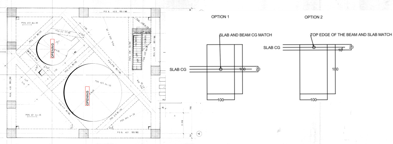
Therefore, I am considering modeling the beams as simple rectangular sections while still ensuring an appropriate beam–slab interaction. Based on the Sofistik tutorials, I am unsure about the correct position of the beam relative to the slab CG. Should the beam CG be aligned with the slab CG (Option 1), should the beam be positioned so that the top edges of the beam and slab coincide (Option 2), or is there another recommended approach?
The two modeling options (Options 1 and 2), along with one of the level layouts, are shown in the figure below for reference.
Additionally, regarding torsional stiffness, my understanding is that the beam torsional stiffness is often reduced to approximately 10% (mostly to prevent the beam from attracting unrealistically large torsional moments, which in reality would be distributed between the beam and the slab). Is this reduction also recommended when modeling in Sofistik, or can the full torsional stiffness (100%) be retained?