Hi,
I have a question for you.
I would be glad if you could answer my questions.
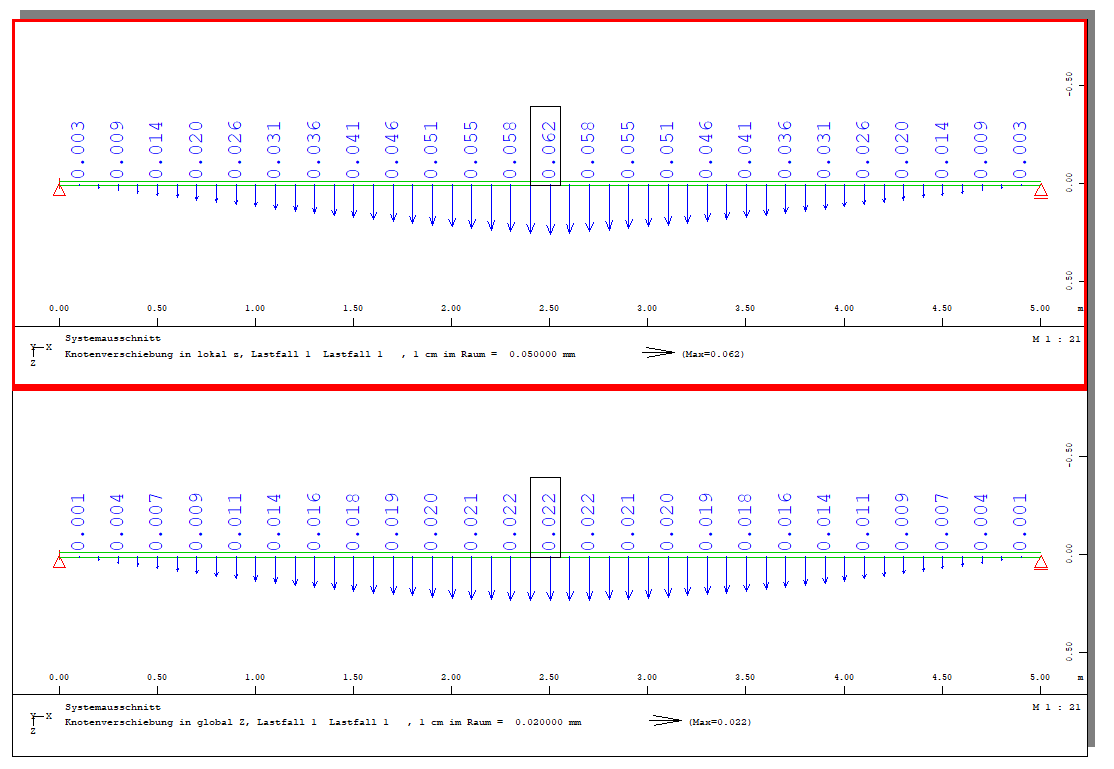
This program is based on a steel I-girder with a load in the y-axis direction applied to the center of the I-girder.
However, the Y-axis displacement of the focus point (Node Number: 60051) differs between the analytical value (0.11mm) and the theoretical value (0.022mm).
Where are the errors in this program?
Here is the analysis code
+PROG AQUA urs:1
HEAD U
UNIT TYPE 7
ECHO MAT
PAGE LANO 1 UNIO 7 UNII 7
MATE NO 1 E 210000 MUE 0.3
END
+PROG SOFIMSHA urs:2
HEAD U
PAGE LANO 1 UNIO 7 UNII 7
SYST REST ; CTRL REST 2 ; CTRL OPTI 50
SYST SPAC GDIR YY GDIV 100000
LET#A 0
LET#B 0
LOOP 101
NODE NO X Y=0 Z=0
1+#A 0+#B
LET#A #A+1
LET#B #B+50
ENDLOOP
TRAN TYPE NODE FROM 1 TO 101 INC 1 DNO 1000 DY -22
LET#A 0
LOOP 5
TRAN TYPE NODE FROM 1+#A TO 101+#A INC 1 DNO 10000 DZ 50
TRAN TYPE NODE FROM 10001+#A TO 10101+#A INC 1 DNO 1000 DY -22
LET#A #A+10000
ENDLOOP
TRAN TYPE NODE FROM 50001 TO 50101 INC 1 DNO 10000 DZ 44
TRAN TYPE NODE FROM 60001 TO 60101 INC 1 DNO 1000 DY -22
TRAN TYPE NODE FROM 60001 TO 60101 INC 1 DNO 10000 DZ 12
TRAN TYPE NODE FROM 70001 TO 70101 INC 1 DNO 1000 DY -22
TRAN TYPE NODE FROM 70001 TO 70101 INC 1 DNO 10000 DZ 44
TRAN TYPE NODE FROM 80001 TO 80101 INC 1 DNO 1000 DY -22
LET#A 0
LOOP 5
TRAN TYPE NODE FROM 80001+#A TO 80101+#A INC 1 DNO 10000 DZ 50
TRAN TYPE NODE FROM 90001+#A TO 90101+#A INC 1 DNO 1000 DY -22
LET#A #A+10000
ENDLOOP
LET#A 0
LOOP 14
TRAN TYPE NODE FROM 1+#A TO 101+#A INC 1 DNO 2000 DY -1978
TRAN TYPE NODE FROM 1001+#A TO 1101+#A INC 1 DNO 2000 DY -1978
LET#A #A+10000
ENDLOOP
LET#A 0
LET#B 0
LOOP 101
NODE NO X Y=-50 Z=294
150001+#A 0+#B
LET#A #A+1
LET#B #B+50
ENDLOOP
TRAN TYPE NODE FROM 150001 TO 150101 INC 1 DNO 20000 DZ 12
LET#B 0
LOOP 2
LET#A 0
LOOP 38
TRAN TYPE NODE FROM 150001+#A+#B TO 150101+#A+#B INC 1 DNO 200 DY -50
LET#A #A+200
ENDLOOP
LET#B #B+20000
ENDLOOP
$$ BRIC $$
LET#B 0
LOOP 13
LET#A 0
LOOP 100
BRIC N1 N2 N3 N4 N5 N6 N7 N8 MNO=1
1+#A+#B 1001+#A+#B 1002+#A+#B 2+#A+#B 10001+#A+#B 11001+#A+#B 11002+#A+#B 10002+#A+#B
LET#A #A+1
ENDLOOP
LET#B #B+10000
ENDLOOP
LET#B 0
LOOP 13
LET#A 0
LOOP 100
BRIC N1 N2 N3 N4 N5 N6 N7 N8 MNO=1
2001+#A+#B 3001+#A+#B 3002+#A+#B 2002+#A+#B 12001+#A+#B 13001+#A+#B 13002+#A+#B 12002+#A+#B
LET#A #A+1
ENDLOOP
LET#B #B+10000
ENDLOOP
LET#A 0
LOOP 100
BRIC N1 N2 N3 N4 N5 N6 N7 N8 MNO=1
61001+#A 150001+#A 150002+#A 61002+#A 71001+#A 170001+#A 170002+#A 71002+#A
LET#A #A+1
ENDLOOP
LET#B 0
LOOP 100
LET#A 0
LOOP 38
BRIC N1 N2 N3 N4 N5 N6 N7 N8 MNO=1
150001+#A+#B 150201+#A+#B 150202+#A+#B 150002+#A+#B 170001+#A+#B 170201+#A+#B 170202+#A+#B 170002+#A+#B
LET#A #A+200
ENDLOOP
LET#B #B+1
ENDLOOP
LET#A 0
LOOP 100
BRIC N1 N2 N3 N4 N5 N6 N7 N8 MNO=1
157601+#A 62001+#A 62002+#A 157602+#A 177601+#A 72001+#A 72002+#A 177602+#A
LET#A #A+1
ENDLOOP
$$ FIX$$
LET#A 0
LOOP 14
NODE 1+#A FIX PP,ZM
NODE 101+#A FIX XP,ZM
LET#A #A+10000
ENDLOOP
END
+PROG SOFILOAD urs:3
HEAD U
PAGE UNII 7 UNIO 7
LET#A 1
LOOP 11
LC #A
LINE REF VGRP TYPE pyy P1 100000 X1 0+500*(#A-1) Y1 -2000 Z1 0 $$
P2 100000 X2 0+500*(#A-1) Y2 -2000 Z2 600
LET#A #A+1
ENDLOOP
END
+PROG ASE urs:4
HEAD U
PAGE UNIO 7 UNII 7
loop 0
LET#A 0
LOOP 11
LC 1+#A
LET#A #A+1
ENDLOOP
endloop
lc 6
END
")