Hi
Autodesk Robot has a feature to redistribute and reduce forces above columns and walls as per EN 1992-1-1 §5.3.2.2.
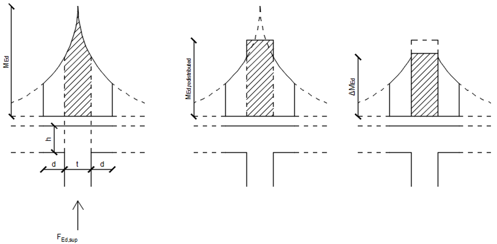
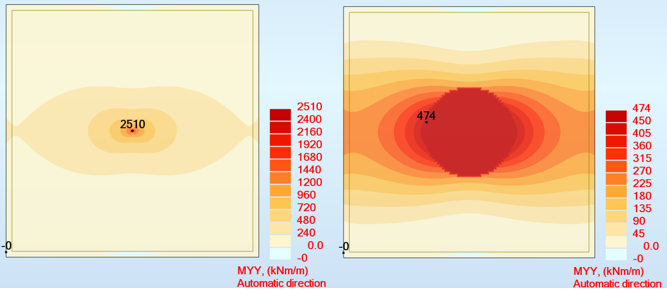
The redistribution in Robot above a circular column is shown below:
Does Sofistik have any similar features?
Hi
Autodesk Robot has a feature to redistribute and reduce forces above columns and walls as per EN 1992-1-1 §5.3.2.2.
The redistribution in Robot above a circular column is shown below:
Does Sofistik have any similar features?
Hello
The reduction of moments over supports can be done, if the width and length of the support section is defined in SOFiMSHC (-> SPT ... BX ... BY...).
→ see BEMESS manual.
SSD / TEDDY > Help > User Manuals > All Manuals… > bemess > 2.5.2 Column Input and Control Paramters
To activate the moment reduction, you must enter the command PUNC. The reduction also works when the punch control is deactivated (PUNC NO).
→ see BEMESS manual chapter 2.5.4 Shear and Bending Desing at the Column
Best regards
Frederik Höller
Your SOFiSTiK Support Team
Thank you for the reply.
I’ve tried to implement bemess as per the manual but I can’t seem to apply it for bending.
Everything seems to be related to the reinforcement, but as per EN, the reinforcement is irrelevant for the redistribution of forces at this point.
Please see the dummy model I’ve made below:
+prog aqua urs:1
    head materials
    NORM DC EN 199X-200X G 10
    conc 1
    stee 2
end
+prog sofimshc urs:2
    head geometry
    SYST 3D GDIV 100000 GDIR NEGZ
    ctrl deln 0
    ctrl mesh 1
    ctrl hmin 10
    unit 6

    spt 1 0     0       0
    spt 2 1000  0       0
    spt 3 1000  1000    0
    spt 4 0     1000    0
    spt 11 500 500 0 fix f bx 200 by 200
    SAR 1 MNO 1 GRP 1 NX 0 0 1  T 200
        SARB TYPE OUT NA 1  NE 2
        SARB TYPE OUT NA 2  NE 3
        SARB TYPE OUT NA 3  NE 4
        SARB TYPE OUT NA 4  NE 1
end
+prog sofiload urs:4
    head loads
    LC 1 type none
    quad grp 1 p 10
end
+prog ase urs:3
    head analysis
    LC 1
end
+prog bemess urs:5
    head reduction
    PUNC NO
    LC 1
end
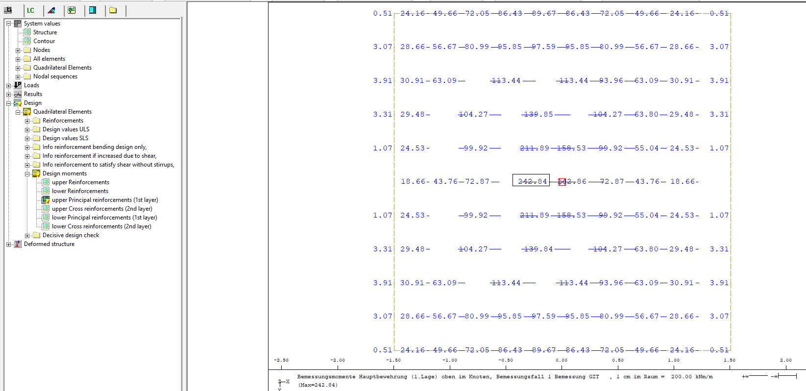
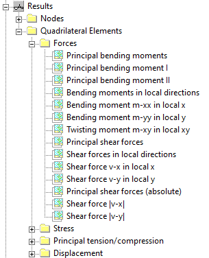
This yields the following options in wingraf:
I’d like to see something like this, but with a “reduced bending moments” as well?
Kind regards
The reason for this is that the moment reduction is carried out in the BEMESS module and not in ASE.
ASE calculates the numerical results of a given FE-system. BEMESS uses the calculated results to design QUAD elements according to the selected design code.
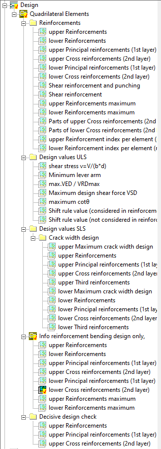
Moment reduction is therefore a tool for post-processing the FE results. These results are then used to calculate the reinforcement. If you want to visualise the design moments, you must select the following graphic.
Graphic > Design > Design moments > e.g. upper principal reinforcements
For an example, please have a look at the TEDDY examples.
TEDDY > File > Examples > bemess > english > bemess2_punching_check.dat
It doesn’t really seem to be what I’m looking for unfortunately.
I ended up creating SLNs along the column border and the connecting those nodes to the support itself. This has the desired effect. Ofcourse the reduced bending moment as per 1992-1-1 §5.3.2.2 is not applied, but I guess I’ll just have to do this in postprocessing.